→ Engineering drawing is an art of representation of an object by systemic line on a paper. Drawing is a Language of engineers.
→ The most important material for drawing is paper and pencil.

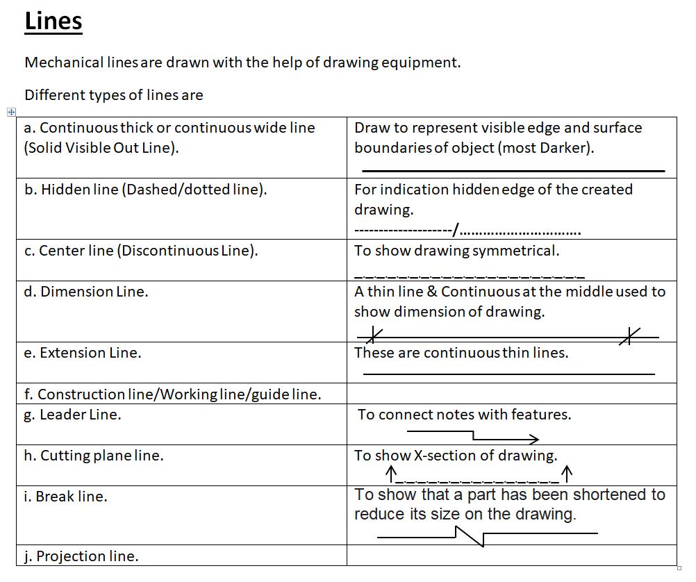
| Note1 a. Hatching is done generally 45o to the mainline of the section. b. R.F = Length of drawing/Actual Length of Object, R.F = <1 (reducing scale), R.F = 1 (full scale), R.F = >1 (enlarging scale). c. Horizontal line is always drawn left to right and vertical line is always drawn top to bottom. d. Slant angle/inclined angle e. Bi-secting of lines means to divide a line into two equal parts. f. During drawing, a drawing we start from top to bottom of drawing paper or left to right of drawing paper. g. The angle between two perpendicular lines is 90o. g. The angle between two horizontal lines is 0o and 180o. h. The main objective of writing a letter on the drawing is to make the drawing more informative and the space between two sentences should be left equal to twice of ht. of the letter. i. The point of intersection of the coordinate axis is called the origin. j. Topographical map is used to represent natural details. |
a. Alined method of dimensioning:- is placed perpendicular to the dimension line in such a way that it may be readable from the bottom and right side of the drawing sheet.
b. Unidirectional method of dimensioning:- is placed in such a way that it may be readable from the only bottom side of the drawing sheet.
| Note2 a. A built drawing is normally constructed after construction and the main purpose is the maintenance of service work. b. Freehand sketch is normally used for concept and done for generating new idea, to make the correction and it is mostly used to express easy to the client. c. Technique for a freehand sketch to drawing a straight line is fixing two endpoints and draw a circle is fixing a fixed point and arc. d. Working drawing is prepared for a bill of quantities, estimation of structure, the layout of the structure, etc. |
a. Triangle:- is obtained when section plane passes through the apex of the cone in such a way that it is perpendicular to the base.
b. Circle:- is obtained when section plane passes parallel to the base of the cone.
c. Ellipse:- is obtained when the section plane is inclined to the axis of the cone and cuts all the generators on either side of the apex.
d. Parabola:- is obtained when the section plane is inclined to the axis of the cone, but parallel to the axis of one of the generators of a cone.
e. Hyperbola:- is obtained when the section plane passes parallel to the base of the cone.
f. Prism:- polyhedra having two equal and similar end bases, parallel to each other and are joined by other faces which may be rectangular or parallelogram.
g. Pyramid:- polyhedra having a plane features for its base and an equal number of isosceles triangle faces a point.
h. Cylinder:- is solid which is generated by the revolution of a rectangle about one of its sides which remains fixed.
i. Cone:- is generated by the revolution of right angle about one of its perpendicular sides which remain fixed.
j. Frustum:- when a pyramid or cone is cut by a cutting plane parallel to its base, the remaining portion is thus obtained after remaining the top portion.
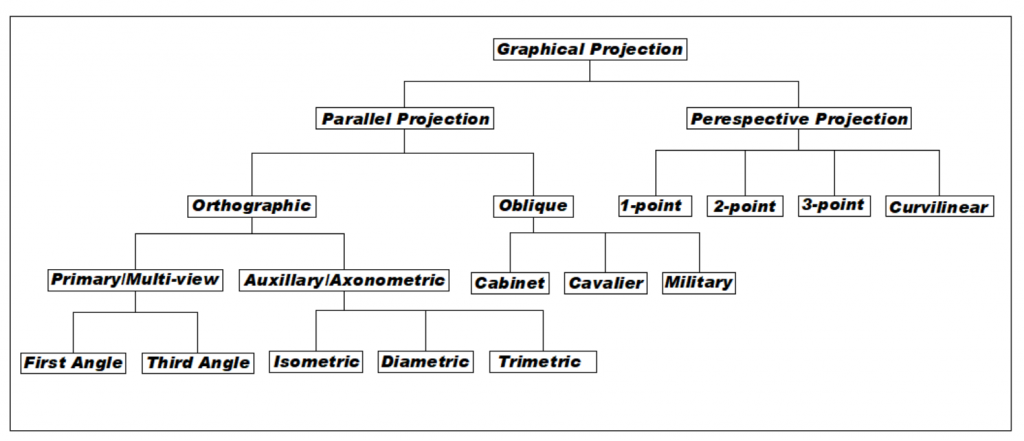
a. Perspective Projection:- is a concept employed to generate images or photographs that look so natural view and vertical plane be represented by horizontal plane radiated from a far situated point. → In this plane picture plane is placed between eye and object. → Perspective drawing is done to show details of market products and it is easy to express in the market (mostly used for 3D games & graphic editing). → Distance of the object from the center of projection is finite and does not produce an accurate view but a realistic representation of an object.
a.a One point projection:- mostly used to draw the images of roads, railway tracks, and buildings.
a.b Two-point projection:- the main use of this is to draw the two corner road.
a.c Three-point projection:- mainly used in skyscraping (difficult to draw).
b. Parallel projection:- in parallel projection, the distance of the project plane from the center of the projection line is infinite. This projection is good for accurate measurement.
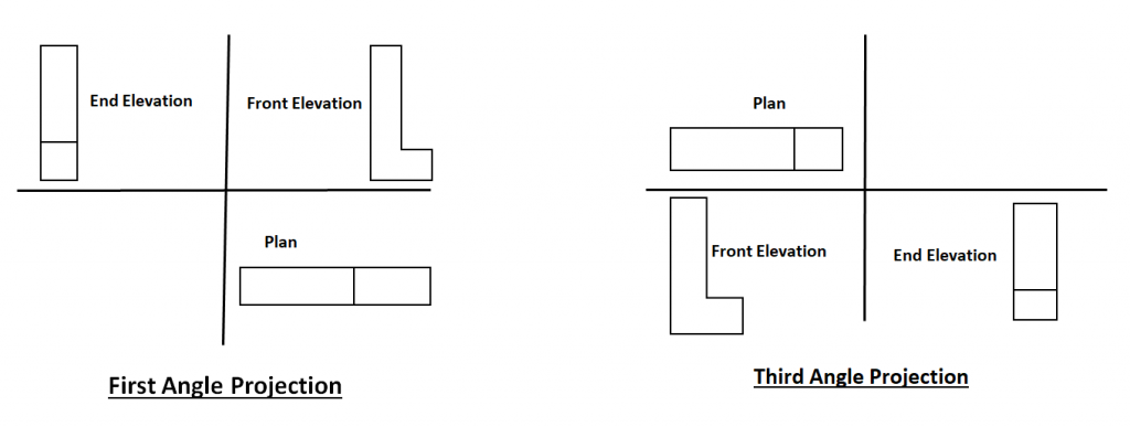
b.a Primary/multiview orthographic projection:- two-dimensional orthographic image into a three-dimensional object that includes front view, side view top view. → Orthographic projection means 90° projection. → It can be further classified as- (First angle projection & Third angle projection)
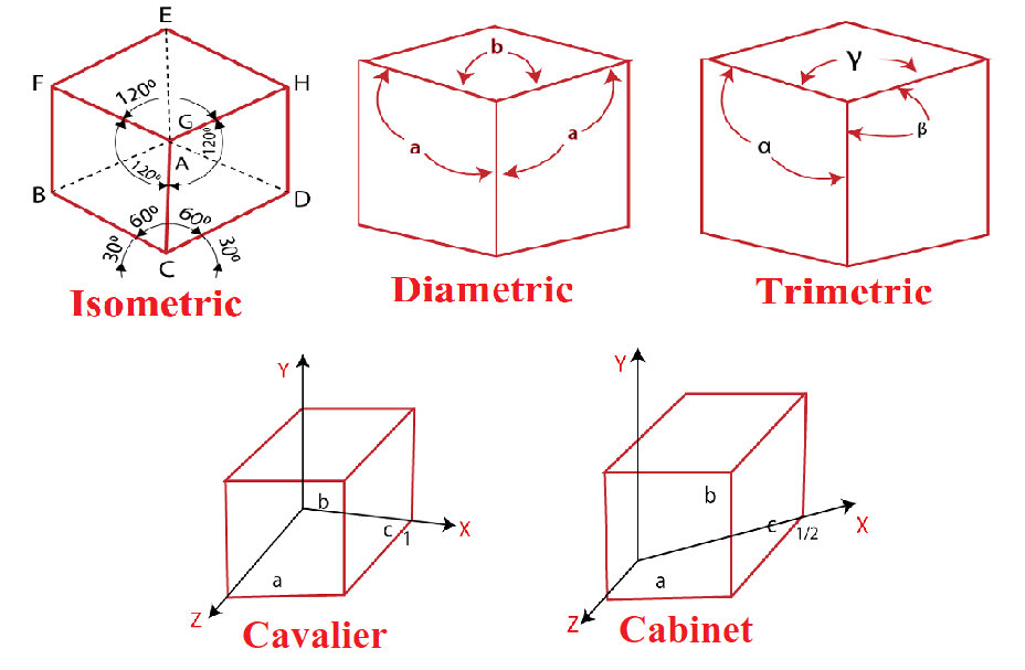
b.b Auxiliary/Axnometric orthographic projection:- is used to construct the pictorial projection of an object. – Sightlines are perpendicular to the project plane.
CIVILBOSS is a free education & learning platform, for the global community of civil engineering students and working professionals, where you can practice multiple choice questions & answers (MCQs), Study Notes, tutorials, Civil Engineering PSC Old Question for Various Level, PSC Exam Crack, Short Question & Answer for Related Particular Topic and Many More. It covers your one-stop destination for job exam preparation with daily practice MCQ and notes.
"Scientists dream about doing great things. Engineers do them."