Fluid mechanics is the branch of science which deals with the behaviour of fluids (liquids or gases) at rest as well as in motion.
This branch of science deals with the static, kinematic and dynamic aspects of fluids.
The study of fluids at rest is called fluid statics.
The study of fluids in motion, where pressure forces are not considered, is called fluid kinematics
and if the pressure forces are also considered for the fluids in motion, that branch of science is called fluid dynamics.

Density or mass density of a fluid is defined as the ratio of the mass of a fluid to its volume. Thus mass per unit volume of a fluid is called density. It is denoted by the symbol ρ (rho). The unit of mass density in SI unit is kg per cubic metre, i.e., kg/m³.
The density of liquids may be considered as constant, while that of gases changes with the variation of pressure and temperature.
Mathematically,
Specific weight or weight density of a fluid is the ratio between the weight of a fluid to its volume. Thus weight per unit volume of a fluid is called weight density, and it is denoted by the symbol w.
The value of specific weight or weight density (w) for water is 9.81 × 1000 Newton/m³ in SI units.
Specific volume of a fluid is defined as the volume of a fluid occupied by a unit mass, or the volume per unit mass of a fluid is called specific volume. Mathematically, it is expressed as;
Thus, specific volume is the reciprocal of mass density. It is expressed as m³/kg. It is commonly applied to gases.
Specific gravity is defined as the ratio of the weight density (or density) of a fluid to the weight density (or density) of a standard fluid. For liquids, the standard fluid is taken as water, and for gases, the standard fluid is taken as air. Specific gravity is also called relative density. It is a dimensionless quantity and is denoted by the symbol S. Mathematically,
If the specific gravity of a fluid is known, then the density of the fluid will be equal to the specific gravity of the fluid multiplied by the density of water. For example, the specific gravity of mercury is 13.6, hence the density of mercury = 13.6 × 1000 = 13600 kg/m³.
Viscosity is defined as the property of a fluid which offers resistance to the movement of one layer of fluid over another adjacent layer of the fluid.
When two layers of a fluid, a distance ‘dy’ apart, move one over the other at different velocities, say u and u + du as shown in Fig. the viscosity together with relative velocity causes a shear stress acting between the fluid layers.
The top layer causes a shear stress on the adjacent lower layer, while the lower layer causes a shear stress on the adjacent top layer. This shear stress is proportional to the rate of change of velocity with respect to y. It is denoted by the symbol τ (Tau).
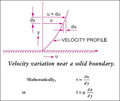
where μ (called mu) is the constant of proportionality and is known as the coefficient of dynamic viscosity, du or only viscosity. du/dy represents the rate of shear strain, or rate of shear deformation or velocity gradient.
It is defined as the ratio between the dynamic viscosity and the density of the fluid. It is denoted by the Greek symbol (v) called ‘nu’. Thus, mathematically,
In MKS and SI, the unit of kinematic viscosity is metre2/sec or m2/sec while in CGS units it is written as cm²/s. In CGS units, kinematic viscosity is also known as a stoke.
It states that the shear stress (t) on a fluid element layer is directly proportional to the rate of shear strain. The constant of proportionality is called the coefficient of viscosity. Mathematically,
Fluids which obey the above relation are known as Newtonian fluids, and fluids which do not obey the above relation are called Non-Newtonian fluids.
Temperature affects the viscosity. The viscosity of liquids decreases with the increase in temperature, while the viscosity of gases increases with the increase in temperature.
This is due to reason that the viscous forces in a fluid are due to cohesive forces and molecular momentum transfer. In liquids, the cohesive forces predominate the molecular momentum transfer, due to closely packed molecules and with the increase in temperature, the cohesive forces decrease the resulting in decreased viscosity.
But in the case of gases, the cohesive forces are small and molecular momentum transfer predominates. With the increase in temperature, molecular momentum transfer increases and hence viscosity increases.
The fluids may be classified into the following five types :
1. Ideal fluid,
2. Real fluid,
3. Newtonian fluid,
4. Non-Newtonian fluid, and
5. Ideal plastic fluid.
1. Ideal Fluid: A fluid which is incompressible and has no viscosity is known as an ideal fluid. Ideal fluid is only an imaginary fluid, as all the fluids which exist have some viscosity.
2. Real Fluid: A fluid which possesses viscosity is known as a real fluid. All the fluids, in actual practice, are real fluids.
3. Newtonian Fluid: A real fluid, in which the shear stress is directly proportional to the rate of shear strain (or velocity gradient), is known as a Newtonian fluid.
4. Non-Newtonian Fluid: A real fluid, in which the shear stress is not proportional to the rate of shear strain (or velocity gradient), known as a Non-Newtonian fluid.
5. Ideal Plastic Fluid: A fluid in which shear stress is more than the yield value and shear stress is proportional to the rate of shear strain (or velocity gradient) is known as an ideal plastic fluid.
Fluids consist of liquids or gases. But gases are compressible fluids, and hence thermodynamic properties play an important role. With the change of pressure and temperature, the gases undergo a large variation in density. The relationship between pressure (absolute), specific volume and temperature (absolute) of a gas is given by the equation of state as
Dimension of R. The gas constant, R, depends upon the particular gas. The dimension of R is obtained from the equation
If the change in density occurs at constant temperature, then the process is called isothermal and the relationship between pressure (p) and density (p) is given by
If the change in density occurs with no heat exchange to and from the gas, the process is called adiabatic. And if no heat is generated within the gas due to friction, the relationship between pressure and density is given by
One kilogram mole is defined as the product of one kilogram mass of the gas and its molecular weight.
Compressibility is the reciprocal of the bulk modulus of elasticity, K, which is defined as the ratio of compressive stress to volumetric strain.
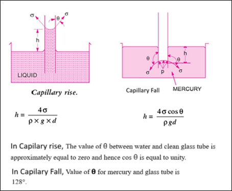
Surface tension is defined as the tensile force acting on the surface of a liquid in contact with a gas or on the surface between two immiscible liquids such that the contact surface behaves like a membrane under tension.
The magnitude of this force per unit length of the free surface will have the same value as the surface energy per unit area. It is denoted by the Greek letter σ (called sigma). In MKS units, it is expressed as kgf/m while in SI units as N/m.
Where,
Capillarity is defined as a phenomenon of rise or fall of a liquid surface in a small tube relative to the adjacent general level of liquid when the tube is held vertically in the liquid.
The rise of the liquid surface is known as capillary rise, while the fall of the liquid surface is known as capillary depression.
It is expressed in terms of cm or mm of liquid. Its value depends upon the specific weight of the liquid, the diameter of the tube and the surface tension of the liquid.
A change from the liquid state to the gaseous state is known as vaporization.
The vaporization (which depends upon the prevailing pressure and temperature conditions) occurs because of the continuous escaping of the molecules through the free liquid surface.
When vaporization takes place, the molecules escape from the free surface of the liquid. These vapour molecules get accumulated in the space between the free liquid surface and the top of the vessel. These accumulated vapours exert a pressure on the liquid surface. This pressure is known as the vapour pressure of the liquid.
If the pressure at any point in this flowing liquid becomes equal to or less than the vapour pressure, the vaporization of the liquid starts. The bubbles of these vapours are carried by the flowing liquid into the region of high pressure, where they collapse, giving rise to high impact pressure.
The pressure developed by the collapsing bubbles is so high that the material from the adjoining boundaries gets eroded and cavities are formed on them. This phenomenon is known as cavitation.
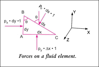
It states that “the pressure or intensity of pressure at a point in a static fluid is equal in all directions”.
i.e Px = Py = Pz
This is proved as: The fluid element is of very small dimensions, i.e., dx, dy and ds.
which states that “the rate of increase of pressure in a vertically downward direction must be equal to the specific weight of the fluid at that point.”
(∂p/∂z) = ρ x g = w
So; p = ρgZ and
Z = P / (ρ x g)
Z is called the pressure head.
The pressure on a fluid is measured in two different systems.
In one system, it is measured above the absolute zero or complete vacuum, and it is called the absolute pressure, and in another system, pressure is measured above the atmospheric pressure, and it is called gauge pressure. Thus:
1. Absolute pressure is defined as the pressure which is measured with reference to absolute vacuum pressure.
2. Gauge pressure is defined as the pressure which is measured with the help of a pressure measuring instrument, in which the atmospheric pressure is taken as datum. The atmospheric pressure on the scale is marked as zero.
3. Vacuum pressure is defined as the pressure below the atmospheric pressure.

Note.
(i) The atmospheric pressure at sea level at 15°C is 101.3 kN/m² or 10.13 N/cm² in SI units. Inthe case of MKS units, it is equal to 1.033 kgf/cm².
(ii) The atmospheric pressure head is 760 mm of mercury or 10.33 m of water.
The pressure of a fluid is measured by the following devices:
1. Manometers
2. Mechanical Gauges.
Manometers are defined as devices used for measuring the pressure at a point in a fluid by balancing the column of fluid by the same or another column of fluid. They are classified as :
(a) Simple Manometers,
(b) Differential Manometers.
Mechanical gauges are defined as devices used for measuring pressure by balancing the fluid column with the spring or dead weight. The commonly used mechanical pressure gauges are :
(a) Diaphragm pressure gauge,
(b) Bourdon tube pressure gauge,
(c) Dead-weight pressure gauge, and
(d) Bellows pressure gauge.
A simple manometer consists of a glass tube having one of its ends connected to a point where pressure is to be measured, and the other end remains open to the atmosphere. Common types of simple manometers are:
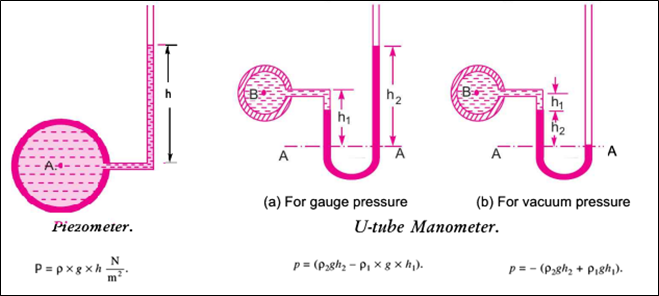
1. Piezometer: It is the simplest form of manometer used for measuring gauge pressures. One end of this manometer is connected to the point where pressure is to be measured, and the other end is open to the atmosphere.
2. U-tube Manometer: It consists of a glass tube bent in a U-shape, one end of which is connected to a point at which pressure is to be measured, and the other end remains open to the atmosphere.
The tube generally contains mercury or any other liquid whose specific gravity is greater than the specific gravity of the liquid whose Pressure is to be measured.
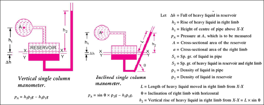
3. Single Column Manometer: A single-column manometer is a modified form of a U-tube manometer in which a reservoir, having a large cross-sectional area (about 100 times) as compared to the area of the tube, is connected to one of the limbs (say, the left limb) of the manometer.
Due to the large cross-sectional area of the reservoir, for any variation in pressure, the change in the liquid level in the reservoir will be very small, which may be neglected, and hence the pressure is given by the height of the liquid in the other limb. The other limb may be vertical or inclined.
Also, known as micrometre, used to measure small pressures where high accuracy is required to measure.
Thus there are two types of single-column manometers:
1. Vertical Single Column Manometer.
2. Inclined Single Column Manometer.
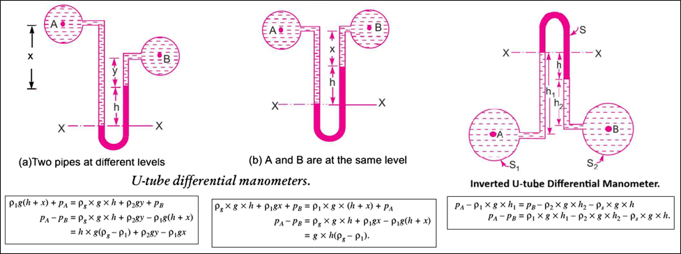
Differential manometers are the devices used for measuring the difference in pressures between two points in a pipe or between two different pipes.
A differential manometer consists of a U-tube, containing a heavy liquid, whose two ends are connected to the points whose difference of pressure is to be measured. The most common types of differential manometers are :
1. U-tube differential manometer and
2. Inverted U-tube differential manometer: It consists of an inverted U-tube, containing a light liquid. The two ends of the tube are connected to the points whose difference in pressure is to be measured. It is used for measuring the difference in low pressures.
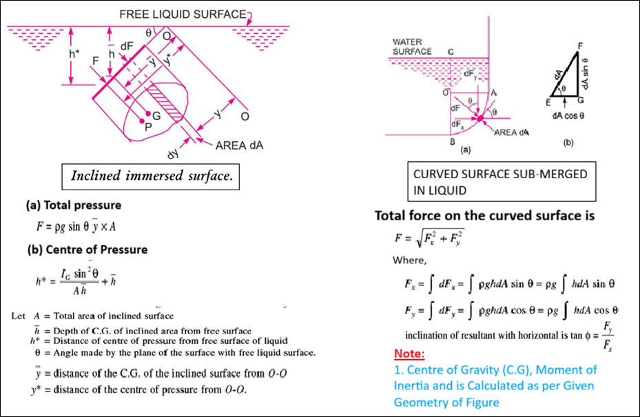
Total pressure is defined as the force exerted by a static fluid on a surface, either plane or curved, when the fluid comes in contact with the surface. This force always acts normally to the surface.
The centre of pressure is defined as the point of application of the total pressure on the surface.
There are four cases of submerged surfaces on which the total pressure force and centre of pressure are to be determined. The submerged surfaces may be:
1. Vertical plane surface,
2. Horizontal plane surface,
3. Inclined plane surface, and
4. Curved surface.

Note:
When a body is immersed in a fluid, an upward force is exerted by the fluid on the body. This upward force is equal to the weight of the fluid displaced by the body and is called the force of buoyancy or simply buoyancy.
other words, the upward force exerted by a liquid on a body when the body is immersed in the liquid is known a buoyancy or force of buoyancy
It is defined as the point through which the force of buoyancy is supposed to act. As the force of buoyancy is a vertical force and is equal to the weight of the fluid displaced by the body, the centre of buoyancy will be the centre of gravity of the fluid displaced.
other words, the point through which the force of buoyancy is supposed to act is called centre of buoyancy.
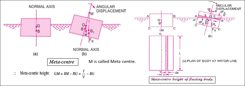
It is defined as the point about which a body starts oscillating when the body is tilted by a small angle. The meta-centre may also be defined as the point at which the line of action of the force of buoyancy will meet the normal axis of the body when the body is given a small angular displacement.
other words, the point about which a body starts oscillating when the body is tilted is known as the meta-centre.
The distance MG, i.e., the distance between the meta-centre of a floating body and the centre of gravity of the body, is called meta-centric height.
A submerged or a floating body is said to be stable if it comes back to its original position after a slight disturbance.
The relative position of the centre of gravity (G) and centre of buoyancy (B₁) of a body determines the stability of a submerged body.
(a) Stability of a Submerged Body: The position of the centre of gravity and centre of buoyancy in the case of a completely submerged body is fixed.
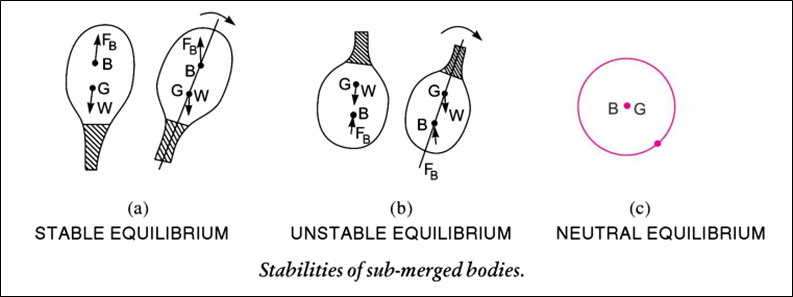
(b) Stability of Floating Body: The stability of a floating body is determined from the position of the Metacentre (M). In the case of a floating body, the weight of the body is equal to the weight of the liquid displaced.

Summary,
| Equillibrum | Floating Body | Sub-merged Body |
| (i) Stable Equillibrum | M is above G | B is above G |
| (iii) Neutral Equilibrium | M is below G | B is below G |
| (iii) Neutral Equilibrum | M and G coincide | B and G coincide |
Kinematics is defined as that branch of science which deals with the motion of particles without
considering the forces causing the motion.
The fluid motion is described by two methods. They are
In the Lagrangian method, a single fluid particle is followed during its motion and its
velocity, acceleration, density, etc., are described.
In the case of the Eulerian method, the velocity, acceleration, pressure, density, etc., are described at a point in the flow field. The Eulerian method is commonly used in fluid mechanics.
The fluid flow is classified as :
(i) Steady and unsteady flows: Steady flow is defined as that type of flow in which the fluid characteristics, like velocity, pressure, density, etc., at a point do not change with time. Unsteady flow is that type of flow in which the velocity, pressure or density at a point changes with respect to time.
(ii) Uniform and non-uniform flows: Uniform flow is defined as that type of flow in which the velocity at any given time does not change with respect to space (i.e., length of direction of the flow). Non-uniform flow is that type of flow in which the velocity at any given time changes with respect to space.
(iii) Laminar and turbulent flows: Laminar flow is defined as that type of flow in which the fluid particles move along well-defined paths or streamlines, and all the streamlines are straight and parallel. Thus, the particles move in laminas or layers, gliding smoothly over the adjacent layer. This type of flow is also called streamline flow or viscous flow.
Turbulent flow is a type of flow in which the fluid particles move in a zig-zag way. Due to the movement of fluid particles in a zig-zag way, the eddies formation takes place, which is responsible for high energy loss.
For a pipe flow, the type of flow is determined by a non-dimensional number VD/v called the Reynolds number,
where D = Diameter of pipe
V = Mean velocity of flow in pipe
and v = Kinematic viscosity of fluid.
If the Reynolds number is less than 2000, the flow is called laminar. If the Reynolds number is more
than 4000, it is called turbulent flow. If the Reynolds number lies between 2000 and 4000, the flow may
be laminar or turbulent.
(iv) Compressible and incompressible flows: Compressible flow is that type of flow in which the density of the fluid changes from point to point, or in other words, the density (ρ) is not constant for the fluid.
Thus, mathematically, for compressible flow
ρ ≠ Constant
Incompressible flow is a type of flow in which the density is constant for the fluid flow. Liquids
are generally incompressible, while gases are compressible. Mathematically, for incompressible flow
ρ = Constant.
(v) Rotational and irrotational flows: Rotational flow is that type of flow in which the fluid particles, while flowing along streamlines, also rotate about their own axis. And if the fluid particles while flowing along streamlines, do not rotate about their own axis, then that type of flow is called irrotational flow.
(vi) One, two and three-dimensional flows: One-dimensional flow is that type of flow in which the flow parameter, such as velocity, is a function of time and one space coordinate only, say x. For a steady one-dimensional flow, the velocity is a function of one spatial coordinate only. The variation of velocities in the other two mutually perpendicular directions is assumed to be negligible. Hence, mathematically, for one-dimensional flow u= f(x), v= 0 and w=0, where u, v and w are velocity components in x, y and z directions, respectively.
Two-dimensional flow is that type of flow in which the velocity is a function of time and two rectangular space co-ordinates, say x and y. For a steady two-dimensional flow, the velocity is a function of two space coordinates only. The variation of velocity in the third direction is negligible. Thus, mathematically, for two-dimensional flow. u=f1(x, y), v=f,(x, y) and w = 0.
Three-dimensional flow is a type of flow in which the velocity is a function of time and three mutually perpendicular directions. But for a steady three-dimensional flow, the fluid parameters are functions of three space co-ordinates (x, y and z) only. Thus, mathematically, for three-dimensional flow u=f(x, y,Z), V=fa(%, y, Z) and w = f3(x, y, Z).
It is defined as the quantity of a fluid flowing per second through a section of a pipe or a channel. For an incompressible fluid (or liquid), the rate of flow or discharge is expressed as the volume of fluid flowing across the section per second.
For compressible fluids, the rate of flow is usually expressed as the weight of fluid flowing across the section. Thus
(i) For liquids, the units of Q are m3/s or litres/s
(ii) For gases, the units of Q are kgf/s or Newton/s
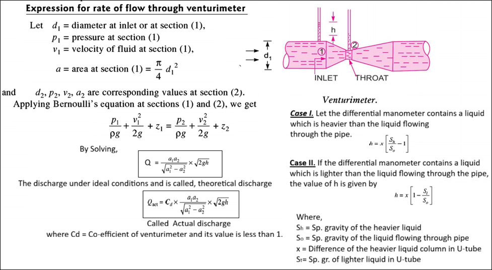
Consider a liquid flowing through a pipe in which
A = Cross-sectional area of pipe
V = Average velocity of fluid across the section
Then discharge (Q) = A x V.
The equation based on the principle of conservation of mass is called the continuity equation. Thus, for a fluid flowing through the pipe at all the cross-sections, the quantity of fluid per second is constant.
Let V1 = Average velocity at cross-section 1-1
ρ1= Density at section 1-1
A1 = Area of pipe at section 1-1
and V2, ρ2, A2, are corresponding values at section 2-2.
Then, the rate of flow at section 1-1 = ρ1A1V1 &
Rate of flow at section 2-2 = ρ2A2V2
So, ρ1A1V1 = ρ2A2V2 ………………….(*)
Equation * applicable to the compressible as well as incompressible fluid.
If the fluid is in- a pipe compressible, then ρ 1 = ρ 2, and continuity reduces to A1V1 = A2V2
Vortex flow is defined as the flow of a fluid along a curved path or the flow of a rotating mass of fluid is known a ‘Vortex Flow’. The vortex flow is of two types, namely:
1. Forced vortex flow: Forced vortex flow is defined as that type of vortex flow in which some external torque is required to rotate the fluid mass. The fluid mass in this type of flow, rotates at constant angular velocity, ω. The tangential velocity of any fluid particle is given by v= ω x r.
e.g., Flow of liquid inside the impeller of a centrifugal pump & through the runner of a turbine.
2. Free vortex flow: When no external torque is required to rotate the fluid mass, that type of flow is called free vortex flow. Thus, the liquid in the case of a free vortex is rotating due to the rotation which is imparted to the fluid previously.
e.g., Flow of liquid through a hole provided at the bottom of a container, Flow of liquid around a circular bend in a pipe, A whirlpool in a river, Flow of fluid in a centrifugal pump casing.
An ideal fluid is a fluid which is incompressible and inviscid. Incompressible fluid is a fluid for which the density (ρ) remains constant. Inviscid fluid is a fluid for which viscosity (μ) is zero. Hence, a fluid for which the density is constant and the viscosity is zero is known as an ideal fluid.
The source flow is the flow coming from a point (source) and moving out radially in all directions of a plane at a uniform rate.
The sink flow is the flow in which fluid moves radially inwards towards a point where it disappears at a constant rate.
The flow patterns due to uniform flow, a source flow, a sink flow and a free vortex flow can be superimposed in any linear combination to get a resultant flow which closely resembles the flow around bodies. The resultant flow will still be potential and ideal. The following are the important Super-imposed flow :
(i) Source and sink pair
(ii) Doublet (special case of source and sink combination)
(iii) A plane source in a uniform flow (flow past a half body)
(iv) A source and sink pair in a uniform flow
(v) A doublet in a uniform flow.
Note:
The dynamic behaviour of the fluid flow is analysed by Newton’s second law of motion, which relates the acceleration to the forces. The fluid is assumed to be incompressible and non-viscous.
According to Newton’s second law of motion, the net force F, acting on a fluid element in the direction of x is equal to the mass m of the fluid element multiplied by the acceleration a, in the x-direction. Thus mathematically, Fx. =m.ax …..(i)
In the fluid flow, the following forces are present :
(i) Fg gravity force.
(ii) Fp the pressure force.
(iii) Fv force due to viscosity.
(iv) Ft force due to turbulence.
(v) Fc force due to compressibility.
Thus in equation (i), the net force
Fx = (Fg)x + (Fp) x + (Pv) x + (Ft) x + (Fc) x ………………..(**)
(i) If the force due to compressibility is negligible, the resulting net force Fx = (Fg)x + (Fp) x + (Pv) x + (Ft) x and the equation of motion are called Reynolds’ equations of motion.
(ii) For flow, where turbulence is negligible, the resulting equations of motion are known as the Navier-Stokes Equation.
(iii) If the flow is assumed to be ideal, the viscous force is zero, and the equations of motion are known as Euler’s equations of motion.
This is the equation of motion in which the forces due to gravity and pressure are taken into consideration. This is derived by considering the motion of a fluid element along a streamline.
(dp/ρ) + gdz + vdv = 0
Is known as Euler’s equation of motion.
Bernoulli’s equation is obtained by integrating the Euler’s equation of motion
If flow is incompressible, ρ is constant and
is a Bernoulli’s equation in which
ASSUMPTIONS
The following are the assumptions made in the derivation of Bernoulli’s equation :
Statement of Bernoulli’s Theorem. It states that in a steady, ideal flow of an incompressible fluid, the total energy at any point of the fluid is constant. The total energy consists of pressure energy, kinetic energy and potential energy or datum energy. These energies per unit weight of the fluid are :
Thus mathematically, Bernoulli’s theorem is written as
The Bernoulli’s equation was derived on the assumption that fluid is inviscid (non-viscous) and therefore frictionless. But all the real fluids are viscous and hence offer resistance to flow.
Thus, there are always some losses in fluid flows, and hence in the application of Bernoulli’s equation, these losses have to be taken into consideration.
Thus, the Bernoulli’s equation for real fluids between points 1 and 2 is given as
Bernoulli’s equation is applied in all problems of incompressible fluid flow where energy considerations are involved. But we shall consider its application to the following measuring devices:
A venturimeter is a device used for measuring the rate of a flow of a fluid flowing through a pipe. It consists of three parts: (i) A short converging part, (ii) the Throat, and (iii) a diverging part. It is based on the Principle of Bernoulli’s equation.
It is a device used for measuring the rate of flow of a fluid through a pipe. It is a cheaper device compared to a venturimeter. It also works on the same principle as that of a venturimeter.
It consists of a flat circular plate which has a circular, sharp-edged hole called an orifice, which is concentric with the pipe.
The orifice diameter is kept generally 0.5 times the diameter of the pipe, though it may vary from 0.4 to 0.8 times the pipe diameter.

It is a device used for measuring the velocity of flow at any point in a pipe or a channel. It is based on the principle that if the velocity of flow at a point becomes zero, the pressure there is increased due to the conversion of the kinetic energy into pressure energy.
Velocity at any point v = Cv √(2gh)
Where, Cv = Coefficient of Pitot-Tube
It is based on the law of conservation of momentum or on the momentum principle, which states that the net force acting on a fluid mass is equal to the change in momentum of flow per unit time in that direction. The force acting on a fluid mass ‘m’ is given by Newton’s second law of motion, F= m.a
Also can be written as F.dt = d(mv)
which is known as the impulse-momentum equation, states that the impulse of a force F acting on a fluid of mass m in a short interval of time dt is equal to the change of momentum d(mv) in the direction of force.
A free liquid jet is defined as the jet of water coming out from the nozzle in the atmosphere. The path travelled by the free jet is parabolic.
An orifice is a small opening of any cross-section (such as circular, triangular, rectangular, etc.) on the side or at the bottom of a tank, through which a fluid flows. it is used to measure rate of flow.
The orifices are classified based on their size, shape, nature of discharge and shape of the upstream edge. The following are the important classifications:
1. The orifices are classified as small orifice or large orifice depending upon the size of the orifice and the head of liquid from the centre of the orifice. If the head of liquid from the centre of the orifice is more than five times the depth of the orifice, the orifice is called a small orifice. And if the head of liquids is less than five times the depth of the orifice, it is known as a large orifice.
2. The orifices are classified as (i) Circular orifice, (ii) Triangular orifice, (iii) Rectangular orifice and (iv) Square orifice depending upon their cross-sectional areas.
3. The orifices are classified as (i) Sharp-edged orifice and (ii) Bell-mouthed orifice depending upon the shape of the upstream edge of the orifices.
4. The orifices are classified as (i) free-discharging orifices and (ii) drowned or submerged orifices depending upon the nature of discharge. The submerged orifices are further classified as (a) Fully submerged orifices and (5) Partially submerged orifices.
The vena contracta is the narrowest point of a jet of fluid after it passes through a constriction, such as a valve or an orifice. At this point, the velocity of the fluid is maximal, and the pressure is minimal, due to the conservation of mass and Bernoulli’s principle.
Q = A x V……(1)
V = √(2gh)……(2)
This is the theoretical velocity. Actual velocity will be less than this value.
a. Co-efficient of Velocity (Cv): is defined as the ratio between the actual velocity of a jet of liquid at vena-contracta and the theoretical velocity of the jet. It is denoted by Cv.
The value of Cv varies from 0.95 to 0.99 for different orifices, depending on the shape, size of the orifice and on the head under which flow takes place. Generally, the value of Cv = 0.98 is taken for sharp-edged orifices.
b. Co-efficient of Contraction (Cc): is defined as the ratio of the area of the jet at vena-contracta to the area of the orifice. It is denoted by Cc.
The value of Cc varies from 0.61 to 0.69 depending on the shape and size of the orifice and the head of liquid under which flow takes place. In general, the value of C. may be taken as 0.64.
c. Co-efficient of Discharge (Cd): is defined as the ratio of the actual discharge from an orifice to the theoretical discharge from the orifice. It is denoted by Cd.
The value of Cd varies from 0.61 to 0.65. For general purpose, the value of Cd is taken as 0.62.
Relation, Cd=Cc x Cv………(*)
DETERMINATION OF CO-EFFIEIENT(a) Coff. of velocity (Cv)
Where,
(b) Coff. of discharge (Cd)
Where,
(c) Coff. of contraction (Cc)
1. Flow through large rectangular orifice
2. Flow through fully submerged orifice
3. Flow through partially submerged orifice
Note:
A mouthpiece is a short length of a pipe which is two to three times its diameter in length, fitted in a tank or vessel containing the fluid. it is used for measuring the rate of flow of fluid.
1. The mouthpieces are classified as
(i) External mouthpiece
(ii) Internal mouthpiece, depending upon their position with respect to the tank or vessel to which they are fitted.
2. The mouthpiece are classified as
(i) Cylindrical mouthpiece
(ii) Convergent mouthpiece
(iii) Convergent-divergent mouthpiece, depending upon their shapes.
3. The mouthpieces are classified as
(i) Mouthpieces running full
(ii) Mouthpieces running free, depending upon the nature of discharge at the outlet of the mouthpiece.
This classification is only for internal mouthpieces which are known Borda’s or Re-entrant mouthpieces.
A mouthpiece is said to be running free if the jet of liquid after contraction does not touch the sides of the mouthpiece.
But if the jet after contraction expands and fills the whole mouthpiece it is known as running full.
Note:
a. The value of Cd, for mouthpiece is more than the value of Cd, for orifice, and so discharge through mouthpiece will be more.
b. Co-efficient of discharge for,
A mouthpiece is a short length of a pipe which is two or three times its diameter in length. If this pipe is fitted externally to the orifice, the mouthpiece is called external cylindrical mouthpiece and the discharge through orifice increases.
Discharge (Q) = = Cd x Area x Velocity = 0.855 x a x √(2gH)
If a mouthpiece converges upto vena-contracta and then diverges then that type of mouthpiece is called Convergent-Divergent Mouthpiece. As in this mouthpiece there is no sudden enlargement of the jet, the loss of energy due to sudden enlargement is eliminated. The coefficient of discharge for this mouthpiece is unity.
Q is given as Q = ac x √(2gH)
where ac = area at vena-contracta.
A short cylindrical tube attached to an orifice in such a way that the tube projects inwardly to a tank, is called an internal mouthpiece. It is also called Re-entrant or Borda’s mouthpiece.
If the length of the tube is equal to its diameter, the jet of liquid comes out from mouthpiece without touching the sides of the tube. The mouthpiece is known as running free.
But if the length of the tube is about 3 times its diameter, the jet comes out with its diameter equal to the diameter of mouthpiece at outlet. The mouthpiece is said to be running full.
a. Borda’s Mouthpiece Running Free
b.Borda’s Mouthpiece Running Full
A notch is a device used for measuring the rate of flow of a liquid through a small channel or a tank. It may be defined as an opening in the side of a tank or a small channel in such a way that the liquid surface in the tank or channel is below the top edge of the opening.
A weir is a concrete or masonary structure, placed in an open channel over which the flow occurs. It is generally in the form of vertical wall, with a sharp edge at the top, running all the way across the open channel.
The notch is of small size while the weir is of a bigger size. The notch is generally made of metallic plate while weir is made of concrete or masonary structure.
1. According to the shape of the opening :
2. According to the effect of the sides on the nappe :
Weirs are classified according to the shape of the opening, the shape of the crest, the effect of the sides on the nappe and nature of discharge.
The following are important classifications.
(a) According to the shape of the opening :
(b) According to the shape of the crest :
(c) According to the effect of sides on the emerging nappe :
A triangular notch or weir is preferred to a rectangular weir or notch due to following reasons :
Note:
5. Fransis’s formula for a rectangular weir is given by:
a. Q = 1.84 × [L − 0.2H] × H3/2 …….for two end contraction
b. Q = 1.84 × L × H3/2 …………………..if contraction are suppressed
c. Q = 1.84 × L × [(H + ha)3/2 − ha3/2] …….if velocity approach is considered
6. Bazins’s formula for a rectangular weir is given by:
a. Q = M × L × √2g × H3/2 …….without velocity approach
b. Q = M × L × √2g × [(H + ha)]3/2 …….without velocity approach
7. A trapezoidal weir with side slope 1:4 is called Cipoletii weir. Discharge through this weir is given by:
8. The discharge over a broad crested weir is given by:
9. The discharge over an ogee weir is given by :
10. The discharge over sub-merged or downed weir is given by:
H = height of water on the upstream side of weir
h = height of water on the downstream side of weir
The flow of fluids which are viscous and flowing at very low viscosity is said to be viscous flow. At low velocity the fluid moves in layers. Each layer of fluid slides over the adjacent layer. Due to relative velocity between two layer the velocity gradient du/dy exists and hence a shear stress 𝜏 = μ(du/dy) act on the layer.
For the flow of viscous fluid through circular pipe, the velocity distribution across a section, the ratio of maximum velocity to average velocity, the shear stress distribution and drop of pressure for a given length is to be determined.
The flow through the circular pipe will be viscous or laminar, if the Reynolds number (R) is less than 2000. The expression for Reynold number is given by:
a. Velocity Distribution.
This shows that the velocity distribution across the section of a pipe is parabolic.
b. Ratio of Maximum Velocity to Average Velocity (when r = 0)
This show that Ratio of maximum velocity to average velocity = 2.0.
c. Drop of Pressure for a given Length (L) of a pipe
d. Shear stress distribution
a. Velocity Distribution
Where,
b. Ratio of Maximum Velocity to Average Velocity
This shows that Ratio of Maximum Velocity to Average Velocity is 3/2 or 1.5
c. Drop of Pressure head for a given Length
If hf is the drop of pressure head, then
d. Shear Stress Distribution.
Shear stress is maximum, when y = 0 or t at the walls of the plates. Shear stress is zero, when y = t/2 that is at the centre line between the two plates.
Kinetic energy correction factor is defined as the ratio of the kinetic energy of the flow per second based on actual velocity across a section to the kinetic energy of the flow per second based on average velocity across the same section. It is denoted by α. Hence mathematically,
It is defined as the ratio of momentum of the flow per second based on actual velocity to the momentum of the flow per second based on average velocity across a section. It is denoted by β. Hence mathematically,
The loss of pressure head, hf in a pipe of diameter D, in which a viscous fluid of viscosity μ is flowing with a velocity is given by Hagen Poiseuille formula
where L = length of pipe
The loss of head due to friction* is given by
Where, f = co-efficient of friction between the pipe and fluid
Equating both equations, then we get,
The following are the experimental methods of determining the co-efficient of viscosity of a liquid:
1. Capillary tube method: in this method, the viscosity of a liquid is calculated by measuring the pressure difference for a given length of the capillary tube. The Hagen Poiseuille law is used for calculating viscosity.
2. Falling sphere resistance method: This method is based on Stoke’s law, according to which the drag force, F on a small sphere moving with a constant velocity, U through a viscous fluid of viscosity, for viscous conditions is given by:
3. By rotating cylinder method: The torque T acting on the cylinder is measured by the torsional spring. The torque the inner cylinder must be equal and opposite to the torque applied on the outer cylinder.
4. Orifice type viscometer: In this method, the time taken by a certain quantity of the liquid whose viscosity is to be determined, to flow through a short capillary tube is noted down.
The co-efficient of viscosity is then obtained by comparing with the co-efficient of viscosity of a liquid whose viscosity is known or by the use conversion factors.
Viscometers such as Saybolt, Redwood or Engler are usually used. The principle for all the three viscometer is same. In the United Kingdom, Redwood viscometer is used while in U.S.A., Saybolt viscometer is commonly used.
Note:-
The apparatus used for determining the viscosity of a liquid is known as viscometer.
When the velocity is increased or fluid is less viscous, the fluid particles do not move in straight paths. The fluid particles move in random manner resulting in general mixing of the particles. This type of flow is called turbulent flow.
A laminar flow changes to turbulent flow when
In case of circular, pipe if Re < 2000 the flow is said to be laminar and if Re > 4000, the flow is said to be turbulent. If Re lies between 2000 to 4000, the flow changes from laminar to turbulent.
The Reynolds Number (Re) is one of the most important dimensionless quantities in fluid mechanics. It is used to predict flow patterns in different fluid flow situations. At its core, the Reynolds Number represents the ratio of Inertial Forces to Viscous Forces.
Variable Definitions:
When a liquid is flowing through a pipe, the velocity of the liquid layer adjacent to the pipe wall is zero. The velocity of liquid goes on increasing from the wall and thus velocity gradient and hence shear stresses are produced in the whole liquid due to viscosity. This viscous action causes loss of energy which is usually known as frictional loss.
On the basis of his experiments, William Froude gave the following laws of fluid fraction for turbulent flow.
The frictional resistance for turbulent flow is:
Loss of Head Due to Friction in Pipes.
Where, f is known as co-efficient of friction.
This equation is known as known as Darcy-Weisbach equation. This equation is commonly used for finding loss of head due to friction in pipes.
Sometimes equation above is written as,
Where, f is known as friction factor.
Note:
1. The co-efficient of friction is given by
2. Loss of pressure head in a laminar flow is proportional to the mean velocity of flow, while in case of turbulent flow it is approximately proportional to the square of velocity.
3. The boundary is known as hydrodynamically smooth if k, the average height of the irregularities projecting from the surface of the boundary is small compared to the thickness of the laminar sub-layer (δ’) and boundary is rough if k is large in comparison with the thickness of the sub-layer.
Or if k/ δ’ < 0.25, the boundary is smooth, if k/ δ’ > 0.6, the boundary is rough and if k/ δ’ is between 0.25 – 6 boundary is in transistion.
The turbulent flow of fluids through pipes running full will be considered. If the pipes are partially full as in the case of sewer lines, the pressure inside the pipe is same and equal to atmospheric pressure. Then the flow of fluid in the pipe is not under pressure.
The loss of head or energy due to friction in a pipe is known as major loss while the loss of energy due to change of velocity of the following fluid in magnitude or direction is called minor loss of energy.
(a) Darcy-Weisbach Formula:
where hf = loss of head due to friction
f = co-efficient of friction which is a function of Reynolds number
L = length of pipe,
V = mean velocity of flow,
d = diameter of pipe.
b. Chezy’s Formula for loss of head due to friction in pipes:
Thus, the loss of head due to friction in pipe from Chezy’s formula can be obtained if the velocity of flow through pipe and also the value of C is known. The value of m for pipe is always equal to d/4.
| a. Loss of Head Due to Sudden Enlargement: |
he =
(V1 – V2)2
2g
|
|
b. Loss of Head Due to Sudden Contraction: if coefficient of contraction Cc is not given then k = 0.5 |
hc =
V22
2g
[
1
Cc
– 1 ]2
=
kV22
2g
, where k = [
1
Cc
– 1 ]2
|
|
c. Loss of Head at the Entrance of a Pipe: This is the loss of energy which occurs when a liquid enters a pipe which is connected to a large tank or reservoir. |
hi = 0.5
V2
2g
|
|
d. Loss of Head at the Exit of Pipe: This is the loss of head (or energy) due to the velocity of liquid at outlet of the pipe. |
ho =
V2
2g
|
| e. Loss of Head Due to an Obstruction in a Pipe: |
=
V2
2g
(
A
Cc(A – a)
– 1 )2
|
|
f. Loss of Head due to Bend in Pipe: The value of k depends on Angle, Radius, and Diameter. |
hb =
kV2
2g
|
|
g. Loss of Head in Various Pipe Fittings: V = velocity, k = coefficient. |
=
kV2
2g
|
It is defined as the line which gives the sum of pressure head (p/w) and datum head (z) of the flowing fluid in a pipe with respect to some reference line or it is the line which is obtained by joining the top of all vertical ordinates, showing the pressure head (p/w) of a flowing fluid in a pipe from the centre of the pipe. It is briefly written as H.G.L. (Hydraulic Gradient Line).
It is defined as the line which gives the sum of pressure head, datum head and kinetic head of a flowing fluid in a pipe with respect to some reference line. It is also defined as the line which is obtained by joining the tops of all vertical ordinates showing the sum of pressure head and kinetic head from the centre of the pipe. It is briefly written as T.E.L. (Total Energy Line).
| Note: 1. Syphon is a long bent pipe which is used to transfer liquid from a reservoir at a higher elevation to another reservoir at a lower level when the two reservoirs are separated by a hill or high level ground. The maximum vacuum created at the summit of syphon is only 7.4 m of water. a. Syphon is used in the following cases: b. To carry water from one reservoir to another reservoir separated by a hill or ridge. c. To take out the liquid from a tank which is not having any outlet. d. To empty a channel not provided with any outlet sluice. |
When pipes of different lengths and different diameters are connected end to end, pipes are called in series or compound pipes. The rate of flow through each pipe connected in series is same. The difference in liquid surface levels is equal to the sum of the total head loss in the pipes.
The difference in liquid surface levels is equal to the sum of the total head loss in the pipes.
Above equation is example considering major head losses (friction) and minor head losses (contraction, enlargement etc,).
If minor losses are neglected, and if the co-efficient of friction is same for all pipe.
When the pipes are connected in parallel, the loss of head in each pipe is same. The rate of flow in main pipe is equal to sum of the rate of flow in each pipe, connected in parallel.
Q = Q1 + Q2
In this, arrangement, the loss of head for each branch pipe is same.
Loss of head for branch pipe 1 = Loss of head for branch pipe 2
It is defined as the pipe of uniform diameter having loss of head and discharge equal to the loss of head and discharge of a compound pipe consisting of several pipes of different lengths and diameters. The uniform diameter of the equivalent pipe is called equivalent size of the pipe. The length of equivalent pipe is equal to sum of lengths of the compound pipe consisting of different pipes.
Total head loss in the compound pipe, neglecting minor losses
Assuming
Discharge
Hence
Known as Dupuit’s equation.
The power transmitted depends upon
Power transmitted through a pipe is maximum when the loss of head due to friction is one-third of the total head at inlet. And maximum efficiency for transmission power is 2/3 i.e 66.7%.
At the other end of the pipe, a valve to regulate the flow of water is provided. When the valve is completely open, the water is flowing with a velocity, V in the pipe.
If now the valve is suddenly closed, the momentum of the flowing water will be destroyed and consequently a wave of high pressure will be set up.
This wave of high pressure will be transmitted along the pipe with a velocity equal to the velocity of sound wave and may create noise called knocking.
Also this wave of high pressure has the effect of hammering action on the walls of the pipe and hence it is also known as water hammer.
The pressure rise due to water hammer depends upon:
The following cases of water hammer in pipes will be considered:
Where,
(i) The valve closure is said to be gradual if T > 2L C
where t = time in sec, C = velocity of pressure wave
(ii) The valve closure is said to be sudden if T < 2L C
where C = velocity of pressure wave.
Where,
| Note: 1. Time Taken by Pressure Wave to Travel from the Valve to the Tank and from Tank to the Valve is 2L/C. 2. A pipe network is an interconnected system of pipes forming several loops or circuits. The examples of such networks of pipes are the municipal water distribution systems in cities and laboratory supply system. Hardy Cross Method is commonly used to determine the pipe network. |
Dimensional analysis is a method of dimensions, in which fundamental dimensions are M, L and T. It is a mathematical technique used in research work for design and for conducting model tests.
It deals with the dimensions of the physical quantities involved in the phenomenon. All physical quantities are measured by comparison, which is made with respect to an arbitrarily fixed value.
Length (L), mass (M) and time (T) are three fixed dimensions which are of importance in Fluid Mechanics. If in any problem of fluid mechanics, heat is involved then temperature is also taken as fixed dimension. These fixed dimensions are called fundamental dimensions or fundamental quantity.
Secondary or derived quantities are those quantities which possess more than one fundamental dimension.
| S. No. | Physical Quantity | Symbol | Dimensions |
|---|---|---|---|
| (a) Fundamental | |||
| 1. | Length | L | L |
| 2. | Mass | M | M |
| 3. | Time | T | T |
| (b) Geometric | |||
| 4. | Area | A | L2 |
| 5. | Volume | ∀ | L3 |
| (c) Kinematic Quantities | |||
| 6. | Velocity | v | LT -1 |
| 7. | Angular Velocity | ω | T -1 |
| 8. | Acceleration | a | LT -2 |
| 9. | Angular Acceleration | α | T -2 |
| 10. | Discharge | Q | L3T -1 |
| 11. | Acceleration due to Gravity | g | LT -2 |
| 12. | Kinematic Viscosity | ν | L2T -1 |
| (d) Dynamic Quantities | |||
| 13. | Force | F | MLT -2 |
| 14. | Weight | W | MLT -2 |
| 15. | Density | ρ | ML-3 |
| 16. | Specific Weight | w | ML-2T -2 |
| 17. | Dynamic Viscosity | μ | ML-1T -1 |
| 18. | Pressure Intensity | p | ML-1T -2 |
| 19. | Modulus of Elasticity |
{
K E |
ML-1T -2 |
| 20. | Surface Tension | σ | MT -2 |
| 21. | Shear Stress | τ | ML-1T -2 |
| 22. | Work, Energy | W or E | ML2T -2 |
| 23. | Power | P | ML2T -3 |
| 24. | Torque | T | ML2T -2 |
| 25. | Momentum | M | MLT -1 |
Dimensional homogeneity means the dimensions of each terms in an equation on both sides are equal. Thus if the dimensions of each term on both sides of an equation are the same the equation is known as dimensionally homogeneous equation. The powers of fundamental dimensions (i.e., L, M, T) on both sides of the equation will be identical for a dimensionally homogeneous equation. Such equations are independent of the system of units.
1. Rayleigh’s method: is used for determining the expression for a variable which depends upon maximum three or four variables only.
2. Buckingham’s π-theorem: The Rayleigh’s method of dimensional analysis becomes more laborious if the variables are more than the number of fundamental dimensions (M, L, T).
This difficulty is overcame by using Buckingham’s π-theorem, which states, “If there are n variables (independent and dependent variables) in a physical phenomenon and if these variables contain m fundamental dimensions (M, L, T), then the variables are arranged into (n-m) dimensionless terms. Each term is called π-term”.
For predicting the performance of the hydraulic structures (such as dams, spillways etc.) or hydraulic machines (such as turbines, pumps etc.), before actually constructing or manufacturing, models of the structures or machines are made and tests are performed on them to obtain the desired information.
The model is the small scale replica of the actual structure or machine. The actual structure or machine is called Prototype. It is not necessary that the models should be smaller than the prototypes (though in most of cases it is), they may be larger than the prototype. The study of models of actual machines is called Model analysis.
Advantages
Similitude is defined as the similarity between the model and its prototype in every respect, which means that the model and prototype have similar properties or model and prototype are completely similar.
Types:
1. Geometric Similarity. The geometric similarity is said to exist between the model and the prototype. The ratio of all corresponding linear dimension in the model and prototype are equal.
2. Kinematic Similarity. Kinematic similarity means the similarity of motion between model and prototype. Thus kinematic similarity is said to exist between the model and the prototype if the ratios of the velocity and acceleration at the corresponding points in the model and at the corresponding points in the prototype are the same.
3. Dynamic Similarity. Dynamic similarity means the similarity of forces between the model and prototype. Thus, dynamic similarity is said to exist between the model and the prototype if the ratios of the corresponding forces acting at the corresponding points are equal. Also, the directions of the corresponding forces at the corresponding points should be same.
Dimensionless numbers are those numbers which are obtained by dividing the inertia force by viscous force or gravity force or pressure force or surface tension force or elastic force.
As this is a ratio of one force to the other force, it will be a dimensionless number. These dimensionless numbers are also called non-dimensional parameters.
1. Reynold’s Number (Re). It is defined as the ratio of inertia force of a flowing fluid and the viscous force of the fluid. The expression for Reynold’s number is obtained as:
By definition, Reynold’s number,
In case of pipe flow, the linear dimension L is taken as diameter, d. Hence pipe flow,
2. Froude’s Number (Fr). The Froude’s number is defined as the square root of the ratio of inertia force of a flowing fluid to the gravity force. Mathematically, it is expressed as
3. Euler’s Number (Eu). It is defined as the square root of the ratio of the inertia force of a flowing fluid to the pressure force. Mathematically, it is expressed as
4. Weber’s Number (We). It is defined as the square root of the ratio of the inertia force of a flowing fluid to the surface tension force. Mathematically, it is expressed as
5. Mach’s Number (M). Mach’s number is defined as the square root of the ratio of the inertia force of a flowing fluid to the elastic force. Mathematically, it is defined as
1. Reynold’s Model Law: Models based on Reynold’s number includes:
2. Froude Model Law: Froude model law is applied in the following fluid flow problems:
3. Euler’s Model Law: Euler’s model law is applicable when the pressure forces are alone predominant in addition to the inertia force.
4. Weber Model Law: Weber model law is applied in following cases:
5. Mach Model Law: Mach modal law are use in following cases
a. Undistorted Models: are those models which are geometrically similar to their prototypes or in other words if the scale ratio for the linear dimensions of the model and its prototype is same, the model is called undistorted model. The behavior of the prototype can be easily predicted from the results of undistorted model.
b. Distorted Models: A model is said to be distorted if it is not geometrically similar to its prototype. For a distorted model different scale ratios for the linear dimensions are adopted. For example, in case of rivers, harbours, reservoirs etc., two different scale ratios, one for horizontal dimensions and other for vertical dimensions are taken.
The following are the advantage of distorted models:
Boundary Layer Flow is defined as the thin region of fluid immediately adjacent to a solid surface (the “boundary”) where the effects of viscosity are significant and the velocity of the fluid is slowed down by friction.
If the Reynold number is more than 5 x 10⁵, the boundary layer is called turbulent boundary layer.
The boundary layer is called laminar boundary layer if the Reynold number of the flow is less than 5 x 10⁵. Where, Re = (U x x)/ ν
And where,
U = free stream velocity of flow.
X = distance from leading edge.
ν = Kinematic viscosity of fluid.
Drag: the component of the total force (FR) exerted by the fluid on the submerged body in the direction of motion is called ‘drag’. This component is denoted by FD. Thus drag is the force exerted by the fluid in the direction of motion.
Lift: the component of the total force (FR) exerted by the fluid in the direction perpendicular to the direction of motion is known as ‘lift’. This is denoted by FL. Thus lift is the force exerted by the fluid in the direction perpendicular to the direction of motion.
When the plane is in steady state, weight of plane is lift force and thrust by engine is drag force.
Terminal Velocity: is the defined as the maximum constant velocity of the falling body with which it will travel. At Terminal Velocity, weight of body is equal to drag force plus buoyant force.
Compressible flow is defined as that flow in which the density of the fluid does not remain constant during flow.
Isothermal Process. This is the process in which a gas is compressed or expanded while the temperature is kept constant.
Adiabatic Process. If the compression or expansion of a gas takes place in such a way that the gas neither gives heat, nor takes heat from its surrounding, then the process is said to be adiabatic.
The basic equations of the compressible flows are
1. Continuity Equation,
2. Bernoulli’s Equation or Energy Equation,
3. Momentum Equation: The momentum per second of a flowing fluid (or momentum flux) is equal to the product of mass per second and the velocity of the flow.
4. Equation of state.
For the compressible fluid flow, Mach number is an important non-dimensional parameter. On the basis of the Mach number, the flow is defined as :
1. Sub-sonic Flow. A flow is said sub-sonic flow if the Mach number is less than 1.0 (or M < 1) which means the velocity of flow is less than the velocity of sound wave (or V < C). (Increase area Velocity decrease).
2. Sonic Flow. A flow is said to be sonic flow if the Mach number (M) is equal to 1.0. This means that when the velocity of flow V is equal to the velocity of sound C, the flow is said to be sonic flow. (Area constant).
3. Super-sonic Flow. A flow is said to be super-sonic flow if the Mach number is greater than 1.0 (or M > 1). This means that when velocity of flow V is greater than the velocity of sound wave, the flow is said to be super-sonic flow. (Increase area velocity also increase)
| Note: 1. In sub-sonic flow, the disturbance always moves ahead of the projectile. In sonic flow, the disturbance moves along the projectile while in super-sonic flow, the projectile always moves ahead of the disturbance. 2. When a fluid is flowing past an immersed body, and at a point on the body if the resultant velocity becomes zero, the values of pressure, temperature and density at that point are called stagnation properties. The point is called the stagnation point. |
The flow of water through a passage under atmospheric pressure is called flow in open channels flow.
If the flow characteristics such as depth of flow, velocity of flow, rate of flow at any point in open channel flow do not change with respect to time, the flow is said to be steady flow
If at any point in open channel flow, the velocity of flow, depth of flow or rate of flow changes with respect to time, the flow is said to be unsteady flow.
If for a given length of the channel, the velocity of flow, depth of flow, slope of the channel and cross-section remain constant, the flow is said to be uniform.
On the other hand, if for a given length of the channel, the velocity of flow, depth of flow etc., do not remain constant, the flow is said to be non-uniform flow.
Non-uniform flow in open channels is also called varied flow, which is classified in the following two types as:
(i) Rapidly Varied Flow (R.V.F.), and
(ii) Gradually Varied Flow (G.V.F.).
Rapidly varied flow (RVF) is defined as that flow in which depth of flow changes abruptly over a small length of the channel. When there is any obstruction in the path of flow of water, the level of water rises above the obstruction and then falls and again rises over a small length of channel.
Gradually Varied Flow (G.V.F.) If the depth of flow in a channel changes gradually over a long length of the channel, the flow is said to be gradually varied flow and is denoted by G.V.F.
The flow in open channel is said to be laminar if the Reynold number (R,) is less than 500 or 600.
If the Reynold number is more than 2000, the flow is said to be turbulent in open channel flow. If Re, lies between 500 to 2000, the flow is considered to be in transition state.
The flow in open channel is said to be sub-critical if the Froude number (Fe) is less than 1.0.
Sub-critical flow is also called tranquil or streaming flow. For sub-critical flow, Fe < 1.0. The flow is called critical if Fe = 1.0.
And if Fe > 1.0, the flow is called super critical or shooting or rapid or torrential.
A. BY CHEZY’S FORMULA
A. BY CHEZY’S FORMULA
∴ Discharge, Q = Area × Velocity = A × V
= A × C√mi
CHEZY’S CONSTANT (C)
= L1/2T−1
1. Bazin formula ( In MKS units) : C = 157.6 1.81 + K √m
2. Ganguillet-Kutter Formula. The value of C is given in MKS unit as
3. Manning’s Formula. The value of C according to this formula is given as
C = 1 N m1/6
m = Hydraulic mean depth
N = Manning’s constant which is having same value as Kutter’s constant for the normal range of slope and hydraulic mean depth.
A section of a channel is said to be most economical when the cost of construction of the channel is minimum.
The discharge, Q will be maximum, when the wetted perimeter P is minimum. This condition will be used for determining the best section of a channel i.e., best dimensions of a channel for a given area.
A. Most Economical Rectangular Channel.
Area (A) = b x d
Perimeter (P) = b + 2d
Hydraulic Mean Depth (m) = A/P
Rectangular channel will be most economical when:
(i) Either b = 2d means width is two times depth of flow.
(ii) Or m= d/2 means hydraulic depth is half the depth of flow.
B. Most Economical Trapezoidal Channel.
Area (A) = (bd+nd)d
Perimeter (P) = 2(b+nd)
Hydraulic Mean Radius (m) = A/P
(i) The side slope is given as 1 vertical to n horizontal.
one side of slope=
(ii) Hydraulic mean depth
Trapezoidal channel will be most economical when:
C. Flow through Circular Channel
Most Economical Circular Section.
1. Condition for maximum velocity
2. Condition for Maximum Discharge
it is defined as the total energy per unit weight of water measured with respect to the channel bottom as the datum.
| Note 1. Specific energy is minimum (discharge maximum) when it is equal to 3/2 times the value of depth of critical flow. 2. Specific Energy Curve: It is defined as the curve which shows the variation of specific energy with depth of flow. a. Alternate Depths: For any given energy E>Emin, the curve shows two possible depths of flow for the same discharge. These are called alternate depths. b. Upper Limb: Represents high depth and low velocity (Subcritical Flow). c. Lower Limb: Represents low depth and high velocity (Supercritical Flow). 3. Critical Depth (hc): Critical depth is defined as that depth of flow of water at which the specific energy is minimum. This is denoted by ‘hc”. 4. Critical Velocity (Vc): The velocity of flow at the critical depth is known as critical velocity. It is denoted by Vc. . 5. Minimum Specific Energy in Terms of Critical Depth 6. Critical Flow: It is defined as that flow at which the specific energy is minimum or the flow corresponding to critical depth is defined as critical flow. Froude number is equal to 1. 7. Streaming Flow or Sub-critical Flow or Tranquil Flow: When the depth of flow in a channel is greater than the critical depth (h,), the flow is said to be sub-critical flow or streaming flow or tranquil flow. For this type of flow the Froude number is less than one i.e., Fe < 1.0. 8. Super-critical Flow or Shooting Flow or Torrential Flow: When the depth of flow in a channel is less than the critical depth (h,), the flow is said to be super-critical flow or shooting flow or torrential flow. For this type of flow the Froude number is greater than one i.e., Fe > 1.0. |
A Hydraulic Jump (also known as a Standing Wave) is one of the most remarkable and important phenomena in open channel flow. It occurs when a high-velocity, shallow stream (supercritical flow) suddenly transitions into a low-velocity, deep stream (subcritical flow).
A hydraulic jump is a sudden, violent rise in the water surface level accompanied by intense turbulence, air entrainment, and significant energy dissipation.
Loss of Energy Due to Hydraulic Jump
Length of Hydraulic Jump: it is is defined as the length between the two sections where one section is taken before the hydraulic jump and the second section is taken immediately after the jump. For a rectangular channel from experiments, it has been found equal to 5 to 7 times the height of the hydraulic jump.
Afflux is defined as the maximum increase in water level due to obstruction in the path of flow of water.
The profile of the rising water on the upstream side of the dam is called back water curve.
The distance along the bed of the channel between the sections where water Starts rising to the section where water is having maximum height is known as length of back water curve.
Hydraulic machines are defined as those machines which convert either hydraulic energy (energy possessed by water) into mechanical energy (which is further converted into electrical energy) or mechanical energy into hydraulic energy.
Turbines are defined as the hydraulic machines which convert hydraulic energy into mechanical energy. This mechanical energy is used in running an electric generator which is directly coupled to the shaft of the turbine.
The following are the important efficiencies of a turbine.
CLASSIFICATION OF HYDRAULIC TURBINES
1. According to the type of energy at inlet:
(a) Impulse turbine, and
(b) Reaction turbine.
2. According to the direction of flow through runner:
(a) Tangential flow turbine,
(b) Radial flow turbine,
(c) Axial flow turbine, and
(d) Mixed flow turbine.
3. According to the head at the inlet of turbine:
(a) High head turbine,
(b) Medium head turbine, and
(c) Low head turbine.
4. According to the specific speed of the turbine:
(a) Low specific speed turbine,
(b) Medium specific speed turbine, and
(c) High specific speed turbine.
| Note: a. If at the inlet of the turbine, the energy available is only kinetic energy, the turbine is known as impulse turbine. b. If at the inlet of the turbine, the water possesses kinetic energy as well as pressure energy, the turbine is known as reaction turbine. c. The Pelton wheel or Pelton turbine is a tangential flow impulse turbine. d. Radial flow turbines are those turbines in which the water flows in the radial direction. e. The inward flow reaction turbine having radial discharge at outlet is known as Francis Turbine. f. If the water flows parallel to the axis of the rotation of the shaft, the turbine is known as axial flow turbine. g. The draft-tube is a pipe of gradually increasing area which connects the outlet of the runner to the tailrace. It is used for discharging water from the exit of the turbine to the tail race. h. Specific speed defined as the speed of a turbine which is identical in shape, geometrical dimensions, blade angles, gate opening etc., with the actual turbine but of such a size that it will develop unit power when working under unit head. i. Unit speed is defined as the speed of a turbine working under a unit head (i.e., under a head of 1 m). j. Unit discharge defined as the discharge passing through a turbine, which is working under a unit head (i.e., 1 m). k. Unit Power is defined as the power developed by a turbine, working under a unit head (i.e., under a head or 1 m). |
If the mechanical energy is converted into pressure energy by means of centrifugal force acting on the fluid, the hydraulic machine is called centrifugal pump.
The following are the main parts of a centrifugal pump:
If the mechanical energy is converted into hydraulic energy (or pressure energy) by sucking the liquid into a cylinder in which a piston is reciprocating (moving backwards and forwards), which exerts the thrust on the liquid and increases its hydraulic energy (pressure energy), the pump is known as reciprocating pump.
Main parts
Slip of a pump is defined as the difference between the theoretical discharge and actual discharge of the pump.
An air vessel is a closed chamber containing compressed air in the top portion and liquid (or water) at the bottom of the chamber.
Work saved by fitting air vessels in a single-acting reciprocating pump is 84.8% while in a double-acting reciprocating pump, the work saved is 39.2%.
Cavitation is defined as the phenomenon of formation of vapour bubbles of a flowing liquid in a region where the pressure of the liquid falls below its vapour pressure and the sudden collapsing of these vapour bubbles in a region of higher pressure.
Precaution against Cavitation
Effects of Cavitation.
The hydraulic machines subjected to cavitation are reaction turbines and centrifugal pumps.
| Note: a. The hydraulic press is a device used for lifting heavy weights by the application of a much smaller force. It is based on Pascal’s law, which states that the intensity of pressure in a static fluid is transmitted equally in all directions. b. The hydraulic accumulator is a device used for storing the energy of a liquid in the form of pressure energy, which may be supplied for any sudden or intermittent requirement. c. The device, which is used to increase the intensity of pressure of water by means of hydraulic energy available from a large amount of water at a low pressure, is called the hydraulic intensifier. d. The hydraulic ram is a pump which raises water without any external power for its operation. It works on the principle of water hammer. e. The hydraulic lift is a device used for carrying passenger or goods from one floor to another in multistoried building f. Hydraulic crane is a device, used for raising or transferring heavy loads. It is widely used in workshops, warehouses and dock sidings. g. The hydraulic torque converter is a device used for transmitting increased torque at the driven shaft. h. The air lift pump is a device which is used for lifting water from a well or sump by using compressed air. i. The triple point of a substance is the unique combination of temperature and pressure at which its three phases—solid (ice), liquid (water), and gas (vapor)—coexist in thermodynamic equilibrium. While the freezing point of water at standard atmospheric pressure is 0 °C, the triple point is slightly higher (0.01 °C) because it occurs at a much lower pressure. Pressure is 611.657 Pa or 6.11657 mba or 0.00603659 atm (about 0.6% of sea-level atmospheric pressure). |
CIVILBOSS is a free education & learning platform, for the global community of civil engineering students and working professionals, where you can practice multiple choice questions & answers (MCQs), Study Notes, tutorials, Civil Engineering PSC Old Question for Various Level, PSC Exam Crack, Short Question & Answer for Related Particular Topic and Many More. It covers your one-stop destination for job exam preparation with daily practice MCQ and notes.
"Scientists dream about doing great things. Engineers do them."