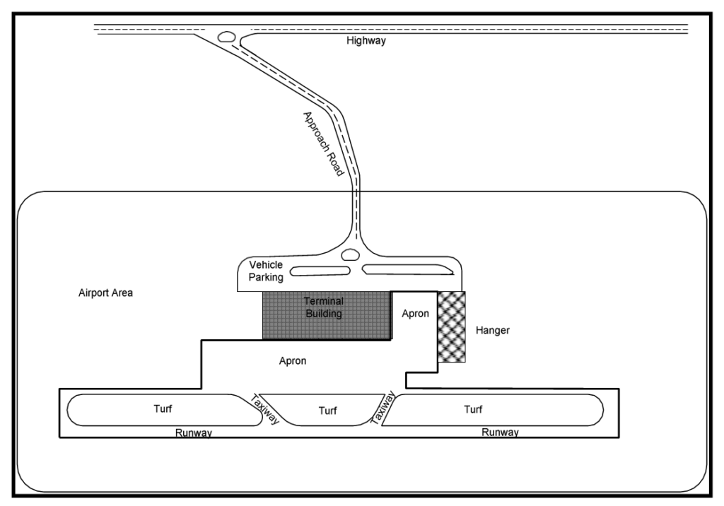
➼ Airport:- any area of land or water used or intended for landing or takeoff of aircraft including appurtenant area used or intended for airport buildings, facilities, as well as rights of way together with the buildings and facilities.

Standards are for
➼ Runway:- Parameters of runway are:
The following factors most strongly influence required runway length.
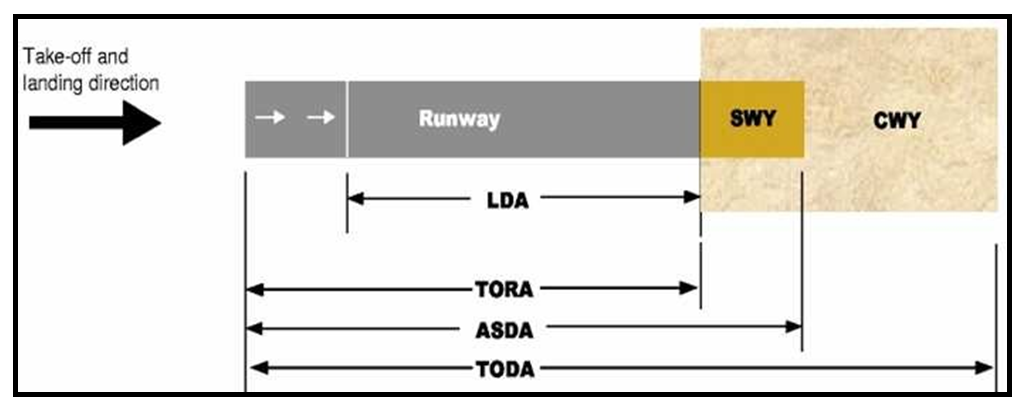
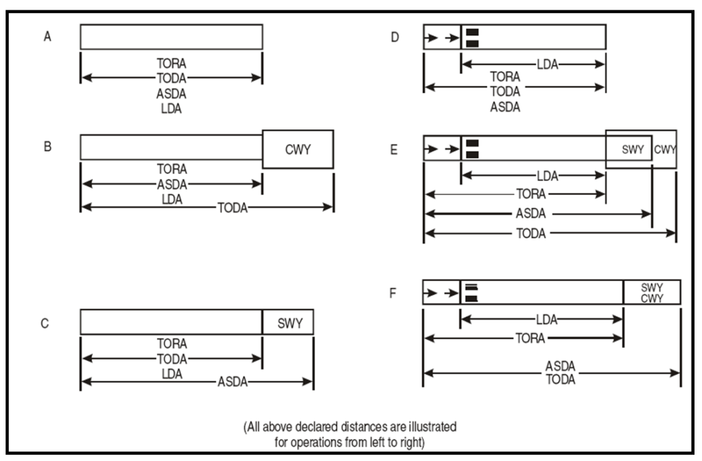
It is the length of runway under the following conditions:
The width of a runway should not be less than the approximate dimension specified in the table below. The factors affecting the width of runway are:
| Code Number | Code Letter | |||||
|---|---|---|---|---|---|---|
| A | B | C | D | E | F | |
| 1a | 18 m | 18 m | 23 m | — | — | — |
| 2a | 23 m | 23 m | 30 m | — | — | — |
| 3 | 30 m | 30 m | 30 m | 45 m | — | — |
| 4 | — | — | 45 m | 45 m | 45 m | 60 m |
The slopes computed by dividing the differences between the maximum and minimum elevation along the runway centerline by the runway length should not exceed:
Along no portion of a runway should the longitudinal slope exceed:
Where slope changes cannot be avoided, a slope change between two consecutive slopes should not exceed:
The transition from one slope to another should be accomplished by a curved surface with a rate of change not exceeding:
Where slope changes cannot be avoided, they should be such that there will be an unobstructed line of sight from:
Undulation or appreciable change in slopes located together along the runway should be avoided. The distance between the points of intersection of two successive curves should not be less than:
Whichever is greater?
To promote the rapid drainage of water, the runway surface should, if practicable, be cambered except where a single cross fall from high to low in the direction of the wind most frequently associated with rain would ensure rapid drainage. The transverse slope should ideally be:
But in any event should not be exceed 1.5 % or 2 %. As applicable, nor be less than 1 % except at runway or taxiway intersections where flatter slopes be necessary.
Runway shoulder must be provided to ensure a transition from the full strength pavement to the unpaved strip of runway. The paved shoulder protects the edge of the runway pavement, contribute to the prevention of soil erosion by jet blast and
mitigate foreign object damage to jet engines. Runways shoulder should be provided for a runway where the code letter is D or E and the runway width is less than 60m. Runway shoulders should be provided where the code letter is F.
The runway shoulders should extend symmetrically on each side of the runway so that the overall width of the runway and its shoulders is not less than 60 m for letter E and 75 m for code letter F.
The surface of the shoulder that abuts the runway should be flush with the surface of the runway and its transverse downward slope should not exceed 2.5 %.
A runway strip extends laterally to a specified distance from the runway center line, longitudinally, before the threshold, and beyond the runway end. It provides an area clear of objects which may endanger aeroplanes.
The strip includes a graded portion which should be so prepared as to not cause the collapse of the nose gear if an aircraft should leave the runway. There are certain limitations on the slopes permissible on graded portion of the strip.
A strip should before the threshold and before the end of the runway or stopway for a distance of at least:
A strip including a precision approach runway shall, wherever practicable, extend laterally for a distance of at least:
A strip including non-precision approach should extend laterally to a distance of at least:
On each side of the centerline of the runway and its extended centerline through the length of the strip
A strip including a non-instrument runway should extend, on each side of the centre line of the runway and its extended centre line throughout the length of the strip, for a distance of at least:
An object, other than equipment or installation required for air navigation purposes, situated on a runway strip which may endanger aeroplanes should be regarded as an obstacle and should, as far as practicable, be removed. Any equipment or installation required for air navigation purposes which must be
located on the runway strip should be of minimum practicable mass and height, frangibly designed and mounted, and sited in such a manner as to reduce the hazard to aircraft to a minimum.
No fixed object, other than visual aids required for air navigation purposes, shall be permitted on a runway strip:
Maximum capacity and efficiency of an aerodrome are realized only by obtaining the proper balance between the need for runways, passenger and cargo terminals, and aircraft storage and servicing areas. These separate and distinct aerodrome functional elements are linked by the taxiway system.
Planning principles of taxiway
| Physical characteristics | Code letter | |||||
|---|---|---|---|---|---|---|
| A | B | C | D | E | F | |
| Minimum width of: | ||||||
| taxiway pavement | 7.5 m | 10.5 m | 18 ma 15 mb |
23 mc 18 md |
23 m | 25 m |
| taxiway pavement and shoulder | — | — | 25 m | 38 m | 44 m | 60 m |
| taxiway strip | 32.5 m | 43 m | 52 m | 81 m | 95 m | 115 m |
| graded portion of taxiway strip | 22 m | 25 m | 25 m | 38 m | 44 m | 60 m |
| Minimum clearance distance of outer main wheel to taxiway edge |
1.5 m | 2.25 m | 4.5 ma 3 mb |
4.5 m | 4.5 m | 4.5 m |
| Minimum separation distance | ||||||
| between taxiway centre line and: | ||||||
| centre line of instrument runway code | ||||||
| number 1 | 82.5 m | 87 m | — | — | — | — |
| number 2 | 82.5 m | 87 m | — | — | — | — |
| number 3 | — | — | 168 m | 176 m | — | — |
| number 4 | — | — | — | 176 m | 182.5 m | 190 m |
| centre line of non-instrument | ||||||
| runway code | ||||||
| number 1 | 37.5 m | 42 m | — | — | — | — |
| number 2 | 47.5 m | 52 m | — | — | — | — |
| number 3 | — | — | 93 m | 101 m | — | — |
| number 4 | — | — | — | 101 m | 107.5 m | 115 m |
| taxiway centre line | 23.75 m | 33.5 m | 44 m | 66.5 m | 80 m | 97.5 m |
| object | ||||||
| taxiwaye | 16.25 m | 21.5 m | 26 m | 40.5 m | 47.5 m | 57.5 m |
| aircraft stand taxilane | 12 m | 16.5 m | 24.5 m | 36 m | 42.5 m | 50.5 m |
| Maximum longitudinal slope of taxiway: | ||||||
| pavement | 3% | 3% | 1.5% | 1.5% | 1.5% | 1.5% |
| change in slope | 1% per 25 m | 1% per 25 m | 1% per 30 m | 1% per 30 m | 1% per 30 m | 1% per 30 m |
| Maximum transverse slope of: | ||||||
| taxiway pavement | 2% | 2% | 1.5% | 1.5% | 1.5% | 1.5% |
| graded portion of taxiway strip upwards | 3% | 3% | 2.5% | 2.5% | 2.5% | 2.5% |
| graded portion of taxiway strip downwards | 5% | 5% | 5% | 5% | 5% | 5% |
| ungraded portion of strip upwards or downwards | 5% | 5% | 5% | 5% | 5% | 5% |
| Minimum radius of longitudinal vertical curve | 2 500 m | 2 500 m | 3 000 m | 3 000 m | 3 000 m | 3 000 m |
| Minimum taxiway sight distance | 150 m from 1.5 m above |
200 m from 2 m above |
300 m from 3 m above |
300 m from 3 m above |
300 m from 3 m above |
300 m from 3 m above |
a. Taxiway intended to be used by aeroplanes with a wheel base equal to or greater than 18 m.
b. Taxiway intended to be used by aeroplanes with a wheel base less than 18 m.
c. Taxiway intended to be used by aeroplanes with an outer main gear wheel span equal to or greater than 9 m.
d. Taxiway intended to be used by aeroplanes with an outer main gear wheel span less than 9 m.
e. Taxiway other than an aircraft stand taxilane.
Changes in direction of taxiways should be as few and small as possible.
| Speed (km/h) |
Radius of curve (m) |
|---|---|
| 16 | 15 |
| 32 | 60 |
| 48 | 135 |
| 64 | 240 |
| 80 | 375 |
| 96 | 540 |
An apron is a defined area intended to accommodate aircraft for purposes of loading and unloading passengers, mail or cargo, fuelling and parking or maintenance. The apron is generally paved but may occasionally be unpaved; for example, in some instances, a turf parking apron may be adequate for small aircraft.
Types
As the elevation increases, the air density reduces. It reduces the lift on the wing of the aircraft and aircraft requires greater ground speed before it can rise into the air. To achieve greater speed longer length of runway is required. ICAO recommends that the basic runway length should be increased at the rate of 7% per 300 m rise in elevation above mean sea level.
The rise in airport reference temperature has the same effect as that of the increase in elevation. Airport reference temperature (Tr) is defined as the monthly mean of average daily temperature (Ta) for the hottest month of the year plus one third the difference of this temperature (Ta) and monthly mean of the maximum daily temperature (Tm) for the same month of the year.
ICAO recommends that the basic length of the runway after having been corrected for elevation should be further increased at the rate of 1 % for every 1° rise of airport reference temperature above the standard atmospheric temperature (Ts) at the elevation. The temperature gradient of the standard atmospheric from the mean sea level to the altitude at which temperature becomes 15° C is -0.0065° C per meter.
Check for total correction for elevation and temperature:
It the total correction (elevation and temperature) exceeds 35% the basic runway length, these corrections should then be checked up by conducting specific studies.
Steeper gradient results in greater consumption of energy, and longer the runway length is required for attaining the ground speed.
ICAO does not recommend on this correction. FAA recommends that the runway length after having been corrected for elevation and temperature should be further increased at the rate of 20% for every 1% of effective gradient.
Effective gradient is defined as the maximum difference in elevation between the highest and lowest points of runway divided by the total length of runway.
Strategic objectives for the period of 2005-2010:
There are different classifications by the related organizations such as ICAO, FAA etc.
| Code element 1 | Code element 2 | |||
|---|---|---|---|---|
| Code number (1) |
Aeroplane reference field length (2) |
Code letter (3) |
Wingspan (4) |
Outer main gear wheel spana (5) |
| 1 | Less than 800 m | A | Up to but not including 15 m | Up to but not including 4.5 m |
| 2 | 800 m up to but not including 1 200 m | B | 15 m up to but not including 24 m | 4.5 m up to but not including 6 m |
| 3 | 1 200 m up to but not including 1 800 m | C | 24 m up to but not including 36 m | 6 m up to but not including 9 m |
| 4 | 1 800 m and over | D | 36 m up to but not including 52 m | 9 m up to but not including 14 m |
| E | 52 m up to but not including 65 m | 9 m up to but not including 14 m | ||
| F | 65 m up to but not including 80 m | 14 m up to but not including 16 m | ||
Military purposes.
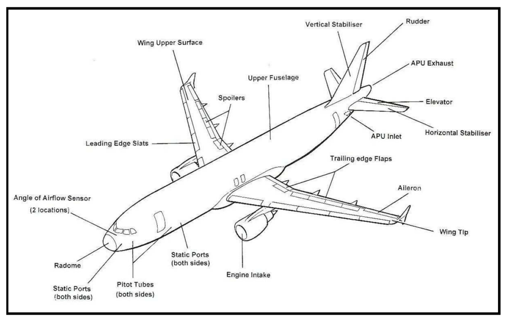
Engine is required to provide the force for propelling the aircraft through the air. According to the method of propulsion aircraft engine can be classified as:
It is powered by gasoline fed reciprocating engine and is driven by propeller or airscrew. Engine rotates a shaft with a considerable amount of torque. Propeller is mounted on the shaft to absorb the torque. Rotating propeller attains its rated speed, huge masses of air is hurled rearwards thereby pulling the aircraft forward and creating lift on the wing. They are suitable to operate at low altitudes and moderate speed. They have cooling problem also.
advantages of jet engines are
a. Turbo Jet: to start the machine, the compressor is rotated with motor. As the compressor gains its rated speed, it sucks in air through the air intake and compresses it in the compression chamber. The air is ignited here by fuel. The expanding gasses pass through the fan like blades of turbine. The hot gasses escape through the tail pipe which becomes smaller in diameter and this hot gas having velocity, give a forward thrust to the engine.
b. Turbo Prop: It is similar to the turbo jet engine except that propeller is provided in it. Turbine extracts enough power to drive both the compressor and propeller.
c. Ram Jet: It has no moving parts. It must be operated at high speed It requires the assistance of other types of power plant to reach the operating speed. The heated air expands and rushes out of the exhaust nozzle at high velocity creating jet thrust.
It produces thrust in the same way as the ram jet engine except it does not depen upon the atmospheric oxygen. There is no limit on altitude.
An airplane can be single engine or multi engined. Single engine usually mounted at the nose of the fuselage. In two or four engined aircraft they usually housed in the leading edge of the aircraft.
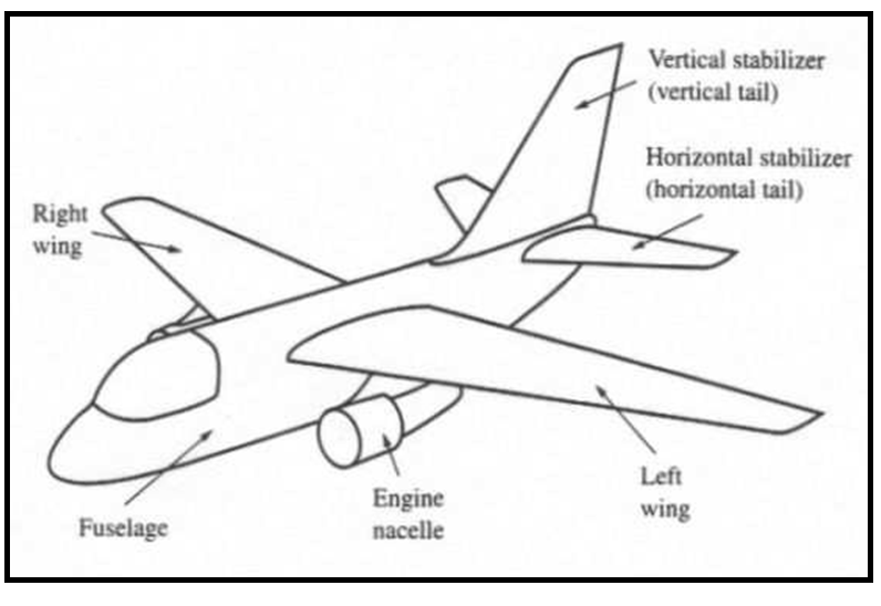
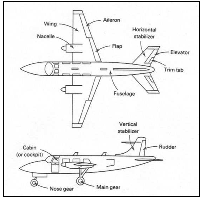
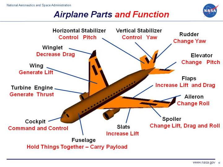
It is main body of the aircraft and provides space for the power plant, fuel, cockpit, passenger, cargo etc.
Wings are required to support the machine in the air, when the engine has given forward speed.
There are three axes about which an aircraft in space may move to control these movements an aircraft is provided with three principal controls:
X axis: rolling movement; Y axis: Pitching; Z axis: Yawing
Tricycle undercarriage if for supporting the aircraft while it is in contact with the ground. Functions:
Types:
- Engine type and propulsion
- Size of aircraft
- Minimum turning radius
- Minimum circling radius
- Speed of aircraft
- Capacity of the aircraft:- baggage, cargo, and fuel accommodated in the aircraft.
- Aircraft weight & wheel configuration
- Jet Blast
- Fuel spillage
Aviation system planning is a process aimed at translating goals and policies into programs that would guide the evolution of the aviation system.
Components of the aviation system:
The aim of the airport system planning is to determine and plan for the scope of development of individual airports within a system in accordance with a scheme which is most likely to fit the individual facilities into an optimal overall development pattern.
Level of planning:
➼ Traffic data:
➼ Demand characteristics:
➼ Airport data:
➼ Supply data:
➼ Socio economic data:
Specific objectives of airport Master Plan:
Suitable site for airport depends upon the class of the airport. Factors to be considered for a suitable airport site are:
The growth in air travel is outstripping the capacity of airport and air traffic control system, resulting in increasing congestion and delay.
The consequences for the air transport industry and traveling public are greater inconvenience, higher costs, declining quality of services and concerns about diminishing safety.
The purpose of capacity analysis is to:
Note:- The capacity analyses make it possible for the airport planner to determine the number of runways, to identify potential configurations, and to compare alternative design.
The term “capacity” refers to the ability of a component of airfield to accommodate aircraft. It is expressed in operations (arrivals and departures) per unit of time, typically in operations per hours.
Thus, the hourly capacity of the runway system is the maximum number of aircraft operations that can be accommodated in one hour under specified operating conditions.
Capacity depends on a number of prevailing conditions, such as visibility, air traffic control, aircraft mix, and type of operations.
Capacity should not be confused with demand. Capacity refers to the physical capability of an airfield and its components. It is measure of supply, and it is independent of both the magnitude and fluctuation of demand and the amount of delay to aircraft.
Delay, however is dependent on capacity and the magnitude and fluctuation in demand. One can reduce aircraft delays by increasing capacity and providing a more uniform pattern of demand.
Runway capacity is normally the controlling element of the airport system capacity.
There are large numbers of factors that influence the capacity of runway system:
a. Air traffic control: FAA specifies minimum vertical, horizontal, and lateral separations for aircraft in the interests of air safety. Since no two airplanes are allowed on the runway at the same time, the runway occupancy time may also influence the capacity.
Example: A runway serves aircraft that land a speed at 165 mph while maintaining the minimum separation of 3 nautical miles as specified by FAA. The average runway occupancy time for landing aircraft is 25 seconds. Determine maximum arrival rate pf the airport. The minimum spacing is (3X6076
= 18228 ft.) in terms of time the minimum arrival spacing is 18228 /(165X5280/3600)= 75 sec. The maximum rate of arrival that can be served by the runway is no more than (3600/75) = 48 arrivals per hour.
b. Characteristics of demand: capacity of runway depends on aircraft size, speed, maneuverability, and braking capability, as well as pilot technique.
c. Environmental conditions: the most important environmental factors influencing capacity are visibility, runway surface conditions, winds, and noise abatement requirements.
d. The layout and design of runway system: for the airport planner, layout and design features comprise the most important class of factors that affect runway capacity. Principal factors in this class include:
- Empirical approaches
- Queuing models
- Analytical approaches
- Computer simulation
Layout of an airport is dependent upon a number of factors the most important are:
Principle facilities to be considered in an airport plan are:
Because of obvious advantages of landing and taking off into the wind, runways are oriented in the direction of prevailing wind.
Aircraft may not maneuver safely on a runway when wind contains large component at right angle to the direction of travel.
The point at which this component (cross wind component) becomes excessive will depend upon the size and operating characteristics of the aircraft.
Factors affecting the determination of the siting, orientation and number of runways:
direction of wind opposite to the direction of landing and takeoff
If landing and takeoff are done along the wind direction, it may require longer runway length.
it is not always possible to obtain the direction of wind along the direction of the center line of runway, this Normal wind component is called cross wind component. And it may interrupt the safe landing and takeoff of the aircraft. VSinθ is the Cross wind Component.
The percentage of time in a year during which the CWC remains within the limit is called Wind Coverage.
Typically wind rose is applied for the orientation of runway.
a. Wind Rose type I: It is the graphical representation of wind data, direction and intensity. Data should be collected for the period of 5 to 10 years. Wind data average of 8 years period. Total % = 86.5. (100 – 86.5 ) = 13.5 % of time wind intensity is less than 6.4 kmph. This period is called Calm Period.
b. Wind Rose type II: In this method a transparent template is prepared for determining the runway orientation. The wind data shown in the table are plotted on a wind rose by replacing the percentage in the appropriate segment of graph. On the wind rose, the circles represent wind velocity in miles per hour and the radial lines indicate wind direction.
The general objective of ATM is to enable aircraft operators to meet their planned times of departure and arrival and adhere to their preferred flight profiles with minimum constraints and without compromising agreed levels of safety.
Objectives of air traffic services
➼ Communication:- is the exchange of voice and data information between the aircraft and air traffic controllers or flight information centers.
➼ Navigation:- Navigation pinpoints the location of aircraft for the crew.
➼ Surveillance:- Surveillance pinpoints the location of the aircraft for Traffic Controller. It includes the communication of navigation information form Aircraft to Air traffic controllers, which facilitates the continuous mapping of the relative position of Aircraft.
| Air Transport in Nepal 1. 1949: The date heralded the formal beginning of aviation in Nepal with the landing of a 4 seater lone powered vintage Beach-craft Bonanza aircraft of Indian Ambassador Mr. Sarjit Singh Mahathia at Gauchar. 2. 1950: The first charter flight By Himalayan Aviation Dakota from Gauchar to Kolkata. 3. 1955: King Mahendra inaugurated Gauchar Airport and renamed it as Tribhuvan Airport. 4. 1957: Grassy runway transformed into a concrete one. 5. 1957: Department of Civil Aviation founded. 6. 1958: Royal Nepal Airlines started scheduled services domestically and externally. 7. 1959: RNAC fully owned by HMG/N as a public undertaking. 8. 1959: Civil Aviation Act 2015 BS. promulgated. 9. 1960: Nepal attained ICAO membership. 10. 1964: Tribhuvan Airport renamed as Tribhuvan International Airport. 11. 1967: The 3750 feet long runway extended to 6600 feet. 12. 1967: Landing of a German Airlines Lufthansa Boeing 707. 13. 1968: Thai International starts its scheduled jet air services. 14. 1972: Nepalese jet aircraft Boeing 727/100 makes a debut landing at TIA. ATC services taken over by Nepalese personnel from Indian technicians. 15. 1975: TIA runway extended to 10000 feet from the previous 6600 feet. 16. 1976: FIC (Flight Information Center) established. 17. 1977: Nepal imprinted in the World Aeronautical Chart. 18. 1989: Completion of International Terminal Building and first landing of Concorde. 19. 1990: New International Terminal Building of TIA inaugurated by King Birendra. 20. 1992: Adoption of Liberal Aviation Policy and emergence of private sector in domestic air transport. 21. 1993: National Civil Aviation Policy promulgated. 22. 1995: Domestic Terminal Building at TIA and Apron Expanded. 23. 1998: CAAN established as an autonomous Authority. 24. 2002: Expansion of the International Terminal Building at TIA and the construction of a new air cargo complex. 25. 2003: Rara airport (Mugu), Kangeldanda airport (Solukhumbu) and Thamkharka airport (Khotang) brought in operation. 26. 2004: Domestic operation by jet aircraft commenced. 27. 2005: International flights by two private operators began. 28. 2006: A new comprehensive Aviation Policy introduced. GMG Airlines of Bangladesh, Korean Air and Air Arabia started air service to Nepal. |
The Tribhuvan International Airport (TIA), situated 5.56 km east of Kathmandu city is in the heart of the Kathmandu Valley
| Coordinates: 274150N – 0852128E Elevation: 4390 ft.AMSL Reference Temperature: 27.8 C Runway Designation: 02/20 Runway Dimension: 10000 ft. x 150 ft. Runway Surface Strength: 54 F/A/W/T Apron Capacity – Int’l: 9 Medium and Wide Body Category Aircraft Domestic: 17 Small Aircraft Helipad: 13 Helicopters Fire Fighting Category: Cat IX Service: Air Traffic Control Service (aerodrome Control, Approach Control and Area Control) Aeronautical communication Service Aeronautical Information Service more detailing please visit TIA site |
Note: Most Dangereous airport in word is Tenzing-Hilary Airport, lies in Lukla, Nepal
1. Distress (Life-threatening emergency)
Primary term: MAYDAY
Example:
“Mayday, Mayday, Mayday, Mumbai Control, Indigo 123 A320, engine failure, landing immediately, position 20 miles east of Mumbai VOR, 6000 feet.”
2. Urgency (Not immediately life-threatening)
Primary term: PAN-PAN
Urgency message format
Similar to distress but less critical.
Additional ICAO Phrases Used in Emergencies
3. Minimum Fuel
4. Mayday Fuel / Fuel Emergency
5. Squawk Codes (Transponder)
Phrase (optional to say verbally):
6. Pilot Incapacitation
Phrase used to alert ATC:
7. Medical Emergencies
8. Fire / Smoke
9. Loss of Cabin Pressure
10. Emergency Landing
11. Ditching (Landing on water)
12. Evacuation
CIVILBOSS is a free education & learning platform, for the global community of civil engineering students and working professionals, where you can practice multiple choice questions & answers (MCQs), Study Notes, tutorials, Civil Engineering PSC Old Question for Various Level, PSC Exam Crack, Short Question & Answer for Related Particular Topic and Many More. It covers your one-stop destination for job exam preparation with daily practice MCQ and notes.
"Scientists dream about doing great things. Engineers do them."