Cement is an extremely fine material having adhesive and cohesive properties which provides a binding medium for the discrete ingredients. various types are
Ordinary portland cement (OPC)
Low heat portland cement
Portland pozzolona cement (PPC)
High alumina cement etc,
➥ Cement concrete: it is a composite material obtained by mixing three ingredients namely coarse aggregate, fine aggregate and cement (PCC).
➥ Reinforced Cement Concrete (RCC): Steel + PCC
➥ advantages of concrete
coefficient of linear expansion of concrete is almost equal to that of steel.
it can be moulded into any shape and size and its ingredient materials are easily available.
it is economical construction and maintenance cost almost nil.
it is fire resistance and its construction is superior to steel and timber.
it is durable and not easily affected by atmospheric agencies.
monolithic construction is possible.
➥ Workability of concrete
it may be defined as the ease with which the concrete may be mixed, handled, transported, placed in position and compacted.
the major factor influencing the workability is the amount of water present in the mix.
➥ Durability of concrete
it is the property of concrete by virtue of which it resists the disintegration and decay of concrete. the disintegration and decay causes due to following;
uses of less durable aggregate that act upon by cement and atmospheric gases.
freezing and thawing of water sucked through cracks causing disintegration of concrete.
expansion and contraction occurring due to temperature changes (wetting and drying).
use of unsound cement which produce changes in hardness concrete.
excessive pores formed while making concrete which permits harmful gases causing disintegration.
note: one of the main characteristics of the concrete influences the durability is its permeability.
➥Gradesof concrete
IS 456 : 2000 specifies 15 grades of concrete that is M10, M15, M20, M25, M30, M35, M40, M45, M50, M55, M60, M65, M70, M75 and M80.
the letter ”M” refers to mix of concrete and numbers follow with “M” refers characteristics strength of concrete in N/mm² (fck) of 150 mm concrete in 28 days.
Characteristics strength may be defined as the strength of concrete below which not more than 5% of the test results are expected to fail that means minimum fck = 0.95 x characteristics strength of concrete.
minimum grade of concrete used in reinforced cement concrete work shall not be less than M20 (as per IS 456 : 2000).
Tensile strength of concrete in flexure fcr = √fck
The modulus of elasticity of concrete Ec = 5000√fck
➥ Water Cement Ratio(W/C ratio)
it is defined as the ratio of the volume of water used to the volume of cement used while making concrete.
the workability and strength of concrete depends upon W/C ratio.
less W/C ratio (below optimum value) causes reduces strength as well as insufficient to complete setting of cement. more W/C ratio (above optimum value) causes increase workability but decrease strength.
Water Cement Ratio for M10 (1:3:6) = 0.6 to 0.65, M15 (1:2:4) = 0.55 to 0.60, M20 (1:1.5:3) = 0.5 to 0.55 and M25 (1:1:2) = 0.45 to 0.5.
➥ Steel
Steel grade are Fe 250 (mild steel), deformed bar(Fe 415, Fe 500, Fe 550) and numerical value with “Fe” denotes characteristics strength (fy) of steel in N/mm2.
the modulus of elasticity of steel “Es” is generally taken as 2 x 10⁵ N/mm2. the characteristics strength of steel below which not more than 5% of the test results are expected to fall.
HYSD (High Yield Strength Deformed Bar) are commonly use with M20 or higher grade of concrete.
➥Reinforced Cement Concrete Design
1.Working Stress Method (WSM):
Factor of safety is taken as 3 for concrete and 1.8 for steel.
also known as modular ratio method. it is traditional method design based on classical elastic theory.
disadvantages;
it does not show the true factor of safety under failure.
it leads uneconomical design.
it fails to distinguish between different types of loads that act simultaneously.
2.Ultimate Load Method (ULM):
stress condition at the state of impending collapse of the structure is analyzed using the non-linear stress strain curve of concrete and steel.
load factor gives factor of safety. in this method, ensures safety at ultimate loads but disregards the service ability at service loads.
3. Limit state Method (LSM):
the area of the normal curve between ∞ and 1.645 is 0.05. Design strength (fd) = fk/ym where;
fk = characteristics strength = fm – 1.645fs
fm = standard deviation of the strength.
➥ partial factor of safety for concrete (ym) = 1.5 and for steel (ym) = 1.15 considered.
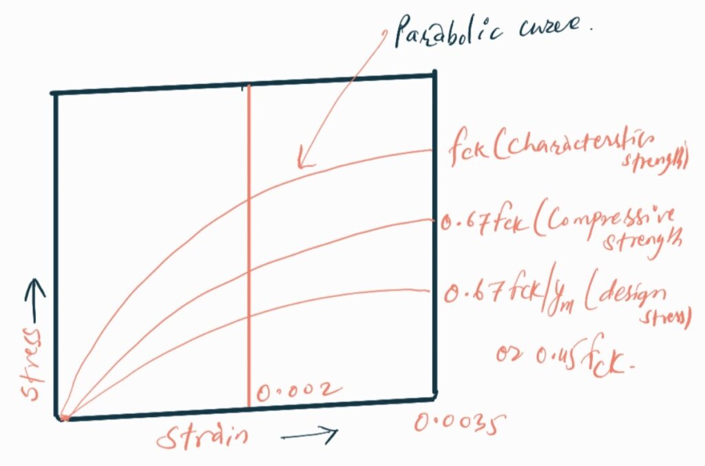
➥ IS 456:2000 suggest that for design purpose the compressive strength of concrete shall be assumed to 0.67 times of characteristics strength of concrete.
Stress Strain Curve
for stress-strain curve of Fe 415 and Fe 500, there is no definite yield point. hence, stress is taken as 0.2% proff stress.
➥ Two types of design should be considered.
a. Limit state of collapse in flexure:
it’s design includes collapse in flexure, in compression, in tension and uniaxial bending (in shear, in bond, in torsion).
b. Limit state of serviceability:
it’s design includes deflection, cracking, vibration, fire resistance, durability etc.
Characteristics Load:
it may defined as that value of load which has a 95% probability of not being exceeded during that life of structure.
Characteristics load (fk) = mean load (fm) + 1.645 x standard deviation of load (fs).
IS code that we follow for load consideration;
dead load (IS 875 part I).
imposed load/live load (IS 875 part II).
wind load (IS 875 part III).
snow load (IS 875 part IV).
seismic/earthquake load (IS 1893).
designed load (fd) = factored load = partial factor of safety x γf x fk.
partial safety factor for load is taken from IS 456:2000 (Table 18).
Limit state of collapse in flexure:
a. singly reinforced rectangular section:
➥ flexural strength of concrete is only about 15% of its compressive strength. to overcome this effect steel is placed in tension zone. the RCC section, which is reinforced only in tension zone, is called single reinforced section.
assumption;
plane section normal to the axis remain plane after bending.
maximum strain in concrete at the outermost compression fibre is taken as 0.0035.
the relationship between compressive stress distribution in concrete and the strain in concrete may be assumed to be rectangular, trapezoidal, parabolic or any shape.
tensile strength of concrete ignored.
stress in steel reinforcement are derived from representative stress-strain curve for the type of steel used.
the maximum strain in the tension reinforcement at failure shall not be less than [(fy/115Es + 0.02)].
lever arm = d – 0.416xu. where, d = depth of beam and xu = depth of neutral axis.
Rebar
Limiting Bending Moment (Mu,lim).
Limiting Moment of Resistance (Ru,lim).
Fe 250
0.1489 fck bd2
0.1489 fck
Fe 415
0.3810 fck bd2
0.3810 fck
Fe 500
0.133 fck bd2
0.133 fck
where; fck = characteristics strength, b = width of beam and d = depth of beam.
➥ Reinforcement ratio (pt) = Ast/bd. where; Ast = area of steel provided.
➥ failure strain in steel Es≥ [(fy/1.15Es) + 0.02].
Balanced section:
balanced section is that one section in which stress in concrete and steel reaches their permissible value at the same time. it is also known as economical section or critical section. it has balanced failure. Es = failure strain.
Under reinforced section:
under reinforced section is that one in which stress in steel reaches its permissible values earlier than concrete. actual neutral axis is shifted above critical neutral axis. it has ductile failure. Es > failure strain.
Over reinforced section:
over reinforced section is that one in which stress in concrete reaches its permissible value earlier than steel. neutral axis is shift below the critical neutral axis. it has brittle failure. Es < failure strain.
Beam Design Requirement:
Effective span = clear span + effective depth.
Stiffness = span / effective depth.
from IS 456:2000; for beam span not exceeding 10 m, stiffness for
cantilever beam≯ 7
simply supported beam≯ 20
continuous beam≯ 26
for span exceeding 10 m, above limit may be multiplied by (10/L), where ‘L’ is span in m.
minimum tension reinforcement: Ast≯ 0.85bd/fy (workout to only 0.2% for Fe 415 and 0.34% for Fe 250.
maximum tension reinforcement: Ast < 0.04bD where; ‘D’ is gross depth of beam.
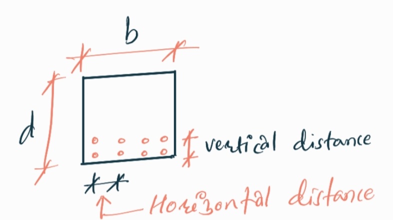
spacing of rebar:
Horizontal spacing: greater of following
dia. of bar if the dia. are equal.
dia. of largest bar if dia. are unequal.
5 mm more than the nominal maximum size of aggregate.
Vertical spacing: greater of following
15 mm
2/3 of nominal maximum size of aggregate.
maximum size of the rebar.
cover reinforcement:
at the end of reinforcement bar not less than 25 mm nor less than twice the dia. of the bar.
for longitudinal reinforcing bar in beam not less than 20 mm nor less than dia. of such bar.
side face reinforcement:
if depth of beam exceeds 750 mm, side face reinforcement shall be provided.
minimum reinforcement 0.1% of beam area shall be provided.
spacing of rebar: whichever is less
300 mm
width of beam.
b. Doubly Reinforced Section:
the doubly reinforced sections are provided under the following situation.
depth of beam is restricted due to architectural and other consideration.
at support of continuous beam where bending moment changes it’s sign.
member which may be subjected to reversal bending moment.
to reduce long term deflection or to increase stiffness.
when ductility of beam is to be improved in earthquake zones etc.
Shear Design:
shear reinforcement is provided to:
prevent shear/brittle shear failure and imparts ductility to members.
guards against concrete cover bursts and loss of bond to the tension steel.
holds the main reinforcement in place and helps in maintaining the requirement of cover for concrete and spacing of reinforcement.
necessary tie for compressive reinforcement.
prevent failure due to shrinkage and thermal stress.
Shear Failure of Beam:
a. Diagonal Tension Failure: occurs near the support where shear force is large as compared to bending moment. the cracks formed due to direct tension makes an angle of 45o with the horizontal.
b. Diagonal Compression Failure: occurs between supports and mid span where shear force as well as bending moment has equal importance. the cracks formed due to this failure makes an angle between 45o to 90o with horizontal.
c. Flexural Tension Failure: occurs at mid span where bending moment is large as compared to shear force. the cracks formed due to this failure makes an angle of 90o with horizontal.
Notes: 1. the c/c spacing of vertical stirrups in beam is minimum near the support. 2. the c/c spacing of vertical stirrups is maximum towards the center of the span of the beam. 3. the c/c spacing of vertical stirrups in beam is minimum at the junction of beam or beam and column. 4. the permissible value of shear stress depends on percentage of steel as well as grade of concrete. 5. the maximum spacing of shear reinforcement shall not exceed 0.75d for vertical stirrups and d forinclined stirrups. where, d as effective depth of beam. 6. a beam is said to be deep beam when the ratio of effective span to overall depth is less than 2 and 2.5 for simply supported beam and continuous beam respectively.
Design for Bond:
the force which acts parallel to the axis of the bar on the interface between reinforcement and surrounding concrete and which prevent slippage between the concrete and the steel is known as bond.
bond force developed due to:
the combined effect of adhesion between concrete and steel.
friction due to shrinkage of concrete.
interlocking of ribs of the steel bar with concrete.
Design bond stress for plain bar in tension (IS 456:2000).
Grade of Concrete
M20
M25
M30
M35
M40 or above
Design bond stress 𝜏bd in N/mm2
1.2
1.4
1.5
1.7
1.9
for deformed bar value are increased by 60% and for bar in compression the value of design bond stress in tension shall be increased by 25%.
thus, the bond stress in compression for plain bar is obtained by multiplying the above table value by 1.25 whereas the bond stress in compression for the deformed bar is obtained by multiplying the above table value by (1.6 x 1.25).
Note: a. the anchorage value of standard U type hook (180o bend) shall be equal to 16 Ø. b. the anchorage value of a standard bend shall be taken as 4 times Ø for each 45o in the bend subjected to a maximum of 16 times of Ø (dia). c. the anchorage value of 90o bend shall be taken as 8 times of Ø of bar. d. the anchorage value of 135o bend shall be taken as 12 times of Ø of bar. e. Equivalent concrete area = modular ratio x area of steel.
Development length: it is the minimum length of bar which must be embedded in concrete beyond any section to develop bond.
Ld = Ø σs/(4 𝜏bd) (in Tension)
Ld = Ø σs/(5 𝜏bd) (in compression)
Splicing of tension reinforcement:
bar dia. above 36 mm, splices should not be used, instead bars may be be welded.
in case of dia. less than 36 mm.
Lap length in flexural tension: Ld or 30 Ø whichever is greater.
Lap length in direct tension: 2Ld or 30 Ø whichever is greater.
Lap length in compression: Ld or 24 Ø whichever is greater.
straight length of lap hook: 15 Ø or 200 whichever is greater.
Steel Beam Theory:
amount of compression reinforcement required equal or exceeds the amount of total tension reinforcement in analysis. the section may be designed using steel beam theory.
compressive resistance provided by the concrete is wholly ignored.
Note: a. in cantilever beam reinforcement should be provided at top side beam (i.e tension reinforcement) to resists tension.
Slab:
simple plane structural member whose thickness is smaller as compared to it’s length and breadth is called slab.
Types:
one way Slab:
{Longer span (ly)/Shorter span (lx)} >2.
minimum reinforcement is provided along the longer span to distribute load uniformly and also to resists the temperature and shrinkage stress.
Two way Slab:
{Longer span (ly)/Shorter span (lx)} ≤ 2.
main reinforcement is provided as both direction.
Basic rule for design of slab:
for simply supported slab:
effective span = clear distance between supports + effective depth of slab or distance between C/C of supports, whichever is less.
in case of mild steel: should not be less than 0.15% of total X-sectional area.
in case of HYSD bar: should not be less than 0.12% of total X-sectional area.
maximum dia. of reinforcing bar shall not exceed 1/8 of total thickness of slab.
horizontal distance between parallel main reinforcement bar shall not be more than:
3 times the effective depth of slab.
300 mm whichever is less.
the horizontal distance between parallel reinforcement bar provided against shrinkage and temperature shall be more than:
5 times the effective depth of slab.
450 mm whichever is less.
the horizontal distance between two parallel main reinforcing bar shall not be less than largest of following:
dia. of bar if dia. are equal.
dia. of largest bar if dia. are unequal.
5 mm more than nominal size of coarse aggregate.
end of reinforcement bar cover shall not be less than:
25 mm
twice of dia. of such such bar, whichever is greater.
bottom cover reinforcement shall not be less than:
20 mm
dia. of bar bar whichever is greater.
Note: Restrained two way slab: slab with their corners prevented from lifting are termed as restrained slab.
Column:
vertical member whose effective length is greater than 3 times its lateral dimension carrying compressive load is called column.
a vertical compression member whose effective length is less than 3 times its least lateral dimension is called pedestal.
an inclined member carrying compressive load is called a strut.
Long Column:
If the ratio of the effective length of the column to its least lateral dimension is greater than 12 then it is called a long column.
Short Column:
If the ratio of effective length to its least lateral dimension is less than or equal to 12 then it is called short column.
Design Consideration for Column:
a. Longitudinal reinforcement for column:
the area of longitudinal reinforcement shall not be less than 0.8% and not more than 6% (4% practically) of the gross sectional area of the column.
the minimum no. of longitudinal bars shall be 4 in case of rectangular column and 6 in case of circular column.
minimum diameter of longitudinal bar is 12 mm.
if any column has larger cross-sectional area than actually required (for other reason), the minimum reinforcement shall be 0.8% of the required area and not the area provided.
spacing of longitudinal bar measured along the periphery shall not exceed 300 mm.
in case of pedestal nominal longitudinal reinforcement shall not be less than 0.15%.
b. Transverse Reinforcement:
the diameter of lateral tiesshall not be less than 1/4th of dia. of the largest longitudinal bar and in no case less than 6 mm.
the pitch of the ties shall not be more than:
least of lateral dimension of column
16 times dia. of smallest longitudinal bar
300 mm.
the pitch of the helical reinforcement shall not be more than:
75 mm.
1/6th of the core diameter.
the pitch of helical reinforcement shall not be less than:
25 mm.
3 times the dia. of helical bar.
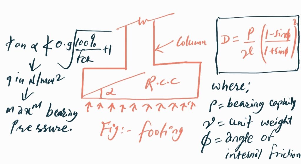
Footing:
the substructure (the portion of structure below ground level) which transmits the load of structure to the supporting soil is known as foundation.
footing is that portion of the foundation which ultimately delivers the load to the soil.
Foundation are provided to ensure:
the pressure intensity on the underlaying soil does not exceed the bearing capacity of soil.
the settlement of the structure is uniform and is within the permissible limit.
the nominal reinforcement for concrete section of thickness greater than 1 m shall be 360 mm2 per meter length in each direction on each face. This provision does not supercode the requirements minimum tensile reinforcement based on the depth of the section.
the bearing capacity of soil can be obtained from the laboratory test on sample collected from the site.
the minimum depth of foundation, according to Rankine theory is given by:
CIVILBOSS is a free education & learning platform, for the global community of civil engineering students and working professionals, where you can practice multiple choice questions & answers (MCQs), Study Notes, tutorials, Civil Engineering PSC Old Question for Various Level, PSC Exam Crack, Short Question & Answer for Related Particular Topicand Many More. It covers your one-stop destination for job exam preparation with daily practice MCQ and notes.
"Scientists dream about doing great things. Engineers do them."